Altivar® 58 TRX AC Drives
Wiring Recommendations
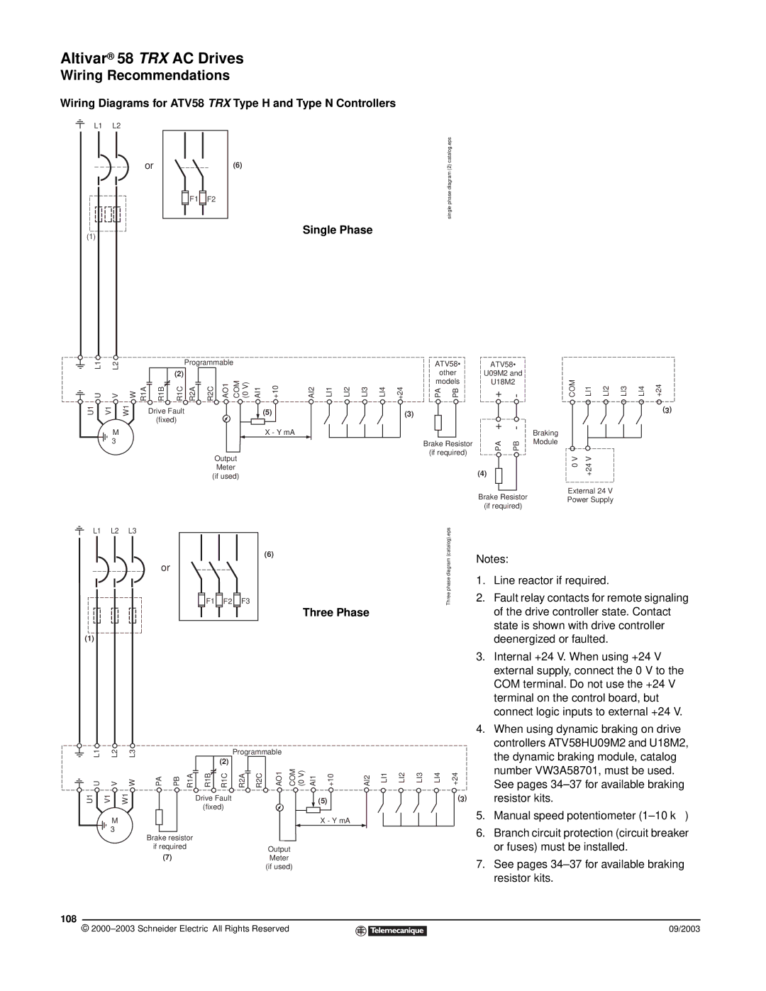
Wiring Diagrams for ATV58 TRX Type H and Type N Controllers
L1 | L2 |
or | (6) |
![]()
![]() F1
F1 ![]()
![]() F2
F2
Single Phase
(1)
single phase diagram (2) catalog.eps
L1 | L2 |
|
| Programmable |
| |||
|
| (2) |
|
|
|
| ||
|
|
|
|
|
|
|
| |
U | V | W R1A | R1B | R1C | R2A | R2C | AO1 | COM (0 V) |
U1 | V1 | W1 | Drive Fault |
|
|
|
| |
|
|
| (fixed) |
|
|
|
| |
M
3φ
Output
Meter
(if used)
|
|
|
|
|
|
|
| ATV58• | ATV58• |
|
|
|
|
|
| ||
|
|
|
|
|
|
|
| other | U09M2 and |
|
|
|
|
|
| ||
AI1 | +10 | AI2 | LI1 | LI2 | LI3 | LI4 | +24 | models | U18M2 | COM | LI1 | LI2 | LI3 | LI4 | +24 | ||
PA | PB | + | - | ||||||||||||||
| (5) |
|
|
|
|
|
| (3) |
|
|
|
|
|
|
|
| (3) |
| X - Y mA |
|
|
|
|
|
|
|
| + | - | Braking |
|
|
|
|
|
|
|
|
|
|
|
|
|
|
|
|
|
|
|
|
| ||
|
|
|
|
|
|
|
| Brake Resistor | PA | PB | Module |
|
|
|
|
| |
|
|
|
|
|
|
|
| (if required) |
|
|
|
|
|
| |||
|
|
|
|
|
|
|
|
|
| 0 V | +24 V |
|
|
|
| ||
|
|
|
|
|
|
|
|
|
| (4) |
|
|
|
|
| ||
|
|
|
|
|
|
|
|
|
| Brake Resistor | External 24 V |
|
|
| |||
|
|
|
|
|
|
|
|
|
| Power Supply |
|
|
| ||||
|
|
|
|
|
|
|
|
|
| (if required) |
|
|
| ||||
|
|
|
|
|
|
|
|
|
|
|
|
|
|
|
| ||
L1 L2 L3
or
(1)
![]()
![]() F1
F1 ![]()
![]() F2
F2 ![]()
![]() F3
F3
(6)
Three phase diagram (catalog).eps
Three Phase
Notes:
1.Line reactor if required.
2.Fault relay contacts for remote signaling of the drive controller state. Contact state is shown with drive controller deenergized or faulted.
3.Internal +24 V. When using +24 V external supply, connect the 0 V to the COM terminal. Do not use the +24 V terminal on the control board, but connect logic inputs to external +24 V.
L1 |
| L2 | L3 |
|
|
|
|
| Programmable |
|
|
|
|
|
|
|
| ||
|
|
|
|
|
|
|
| (2) |
|
|
|
|
|
|
|
|
|
|
|
U |
| V | W | PA | PB | R1A | R1B | R1C | R2A | R2C | AO1 | COM (0 V) | AI1 | +10 | AI2 | LI1 | LI2 | LI3 | LI4 |
U1 | V1 | W1 |
|
|
|
| Drive Fault |
|
|
|
|
| (5) |
|
|
|
|
| |
|
|
|
|
|
|
| (fixed) |
|
|
|
|
|
|
|
|
|
|
| |
|
| M |
|
|
|
|
|
|
|
|
|
|
| X - Y mA |
|
|
|
|
|
|
| 3 φ |
| Brake resistor |
|
|
|
|
|
|
|
|
|
|
|
|
| ||
|
|
|
|
|
|
|
|
|
|
|
|
|
|
|
|
| |||
|
|
|
| if required |
|
|
|
|
| Output |
|
|
|
|
|
|
| ||
|
|
|
|
| (7) |
|
|
|
|
|
|
|
|
|
|
|
| ||
|
|
|
|
|
|
|
|
|
| Meter |
|
|
|
|
|
|
|
| |
|
|
|
|
|
|
|
|
|
|
| (if used) |
|
|
|
|
|
|
| |
108
©
4. | When using dynamic braking on drive | |
| controllers ATV58HU09M2 and U18M2, | |
| the dynamic braking module, catalog | |
+24 | number VW3A58701, must be used. | |
See pages | ||
| ||
(3) | resistor kits. | |
5. | Manual speed potentiometer | |
6. | Branch circuit protection (circuit breaker | |
| or fuses) must be installed. | |
7. | See pages | |
| resistor kits. |
09/2003