|
|
|
|
|
|
|
| Altivar® 58 TRX AC Drives | |
|
|
|
|
|
|
|
| Communication Parameters | |
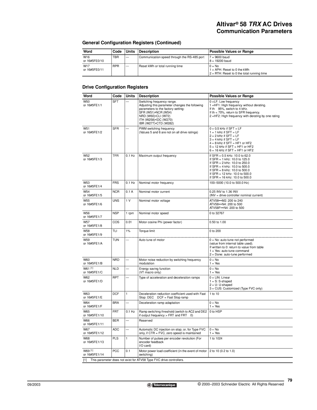
| General Configuration Registers (Continued) |
|
|
| |||||
|
|
|
|
|
| ||||
| Word | Code | Units | Description | Possible Values or Range | ||||
|
|
|
|
|
| ||||
| W16 | TBR | — | Communication speed through the | 7 = 9600 baud | ||||
| or 16#5FE0/10 |
|
|
|
|
| 8 | = 19200 baud | |
|
|
|
|
|
| ||||
| W17 | RPR | — | Reset kWh or total running time | 0 = No | ||||
| or 16#5FE0/11 |
|
|
|
|
| 1 | = APH: Reset to 0 the kWh | |
|
|
|
|
|
|
| 2 | = RTH: Reset to 0 the total running time | |
|
|
|
|
|
|
|
| ||
| Drive Configuration Registers |
|
|
| |||||
|
|
|
|
|
| ||||
| Word | Code | Units | Description | Possible Values or Range | ||||
|
|
|
|
|
|
| |||
| W50 | SFT | — | Switching frequency range. | 0 | =LF: Low frequency | |||
| or 16#5FE1/1 |
|
| Adjusting this parameter changes the following | 1 | =HF1: High frequency without derating. | |||
|
|
|
| parameters to the factory setting: | If th ≥ 95%, switch to 4 kHz. | ||||
|
|
|
| SFR (W51)•NCR (W54) | If th < 70%, return to SFR frequency. | ||||
|
|
|
| NRD (W60)•CLI (W72) | 2 | =HF2: High frequency with derating by one rating | |||
|
|
|
| ITH (W258)•IDC (W270) |
|
|
| ||
|
|
|
| IBR (W277)•CTD (W282) |
|
|
| ||
|
|
|
|
|
|
| |||
| W51 | SFR | — | PWM switching frequency | 0 | = 0.5 kHz if SFT = LF | |||
| or 16#5FE1/2 |
|
| (Values 5 and 6 are not on all drive ratings) | 1 | = 1 kHz if SFT = LF | |||
|
|
|
|
|
|
| 2 | = 2 kHz if SFT = LF | |
|
|
|
|
|
|
| 3 | = 4 kHz if SFT = LF | |
|
|
|
|
|
|
| 4 | = 8 kHz if SFT = HF1 or HF2 | |
|
|
|
|
|
|
| 5 | = 12 kHz if SFT = HF1 or HF2 | |
|
|
|
|
|
|
| 6 | = 16 kHz if SFT = HF1 or HF2 | |
|
|
|
|
|
| ||||
| W52 | TFR | 0.1 Hz | Maximum output frequency | If SFR = 0.5 kHz: 10.0 to 62.0 | ||||
| or 16#5FE1/3 |
|
|
|
|
| If SFR = 1 kHz: 10.0 to 125.0 | ||
|
|
|
|
|
|
| If SFR = 2 kHz: 10.0 to 250.0 | ||
|
|
|
|
|
|
| If SFR = 4 kHz: 10.0 to 500.0 | ||
|
|
|
|
|
|
| If SFR = 8 kHz: 10.0 to 500.0 | ||
|
|
|
|
|
|
| If SFR = 12 kHz: 10.0 to 500.0 | ||
|
|
|
|
|
|
| If SFR = 16 kHz: 10.0 to 500.0 | ||
|
|
|
|
|
| ||||
| W53 | FRS | 0.1 Hz | Nominal motor frequency | |||||
| or 16#5FE1/4 |
|
|
|
|
|
|
|
|
|
|
|
|
|
| ||||
| W54 | NCR | 0.1 A | Nominal motor current | 0.25 INV to 1.36 INV | ||||
| or 16#5FE1/5 |
|
|
|
|
| (INV = drive controller nominal current) | ||
|
|
|
|
|
| ||||
| W55 | UNS | 1 V | Nominal motor voltage | ATV58•••M2: 200 to 240 | ||||
| or 16#5FE1/6 |
|
|
|
|
| ATV58•••N4: 200 to 500 | ||
|
|
|
|
|
|
| ATV58F•••N4: 200 to 500 | ||
|
|
|
|
|
| ||||
| W56 | NSP | 1 rpm | Nominal motor speed | 0 to 32767 | ||||
| or 16#5FE1/7 |
|
|
|
|
|
|
|
|
|
|
|
|
|
| ||||
| W57 | COS | 0.01 | Motor cosine Phi (power factor) | 0.50 to 1.00 | ||||
| or 16#5FE1/8 |
|
|
|
|
|
|
|
|
|
|
|
|
|
| ||||
| W58 | TLI | 1% | Torque limit | 0 to 200 | ||||
| or 16#5FE1/9 |
|
|
|
|
|
|
|
|
|
|
|
|
|
| ||||
| W59 | TUN | — | 0 = No: | |||||
| or 16#5FE1/A |
|
|
|
|
| (value from internal table used). | ||
|
|
|
|
|
|
| If written to 0: return to value from table | ||
|
|
|
|
|
|
| 1 | = Yes: | |
|
|
|
|
|
|
| 2 | = Done: | |
|
|
|
|
|
|
| |||
| W60 | NRD | — | Motor noise reduction by switching frequency | 0 | = No | |||
| or 16#5FE1/B |
|
| modulation | 1 | = Yes | |||
|
|
|
|
|
|
| |||
| W61 [1] | NLD | — | Energy saving function | 0 | = No | |||
| or 16#5FE1/C |
|
| (VT macro only) | 1 | = Yes | |||
|
|
|
|
|
| ||||
| W62 | RPT | — | Type of acceleration and deceleration ramps | 0 = LIN: Linear | ||||
| or 16#5FE1/D |
|
|
|
|
| 1 | = S: | |
|
|
|
|
|
|
| 2 | = U: | |
|
|
|
|
|
|
| 3 | = CUS: Customized (Type FVC only) | |
|
|
|
|
|
| ||||
| W63 | DCF | 1 | Deceleration reduction coefficient used with Fast | 1 to 10 | ||||
| or 16#5FE1/E |
|
| Stop: DEC ⎟ DCF = Fast Stop ramp |
|
|
| ||
|
|
|
|
|
| ||||
| W64 | BRA | — | Deceleration ramp adaptation | 0 = No | ||||
| or 16#5FE1/F |
|
|
|
|
| 1 | = Yes | |
|
|
|
|
|
| ||||
| W65 | FRT | 0.1 Hz | Ramp switching threshold (switch to AC2 and DE2 | 0 to HSP | ||||
| or 16#5FE1/10 |
|
| if output frequency > FRT and FRT ≠ 0) |
|
|
| ||
|
|
|
|
|
|
|
| ||
| W66 | BER | — | Reserved |
|
|
| ||
| or 16#5FE1/11 |
|
|
|
|
|
|
|
|
|
|
|
|
|
|
| |||
| W67 | ADC | — | Automatic DC injection on stop; or, for Type FVC | 0 | = No | |||
| or 16#5FE1/12 |
|
| only, if CTR = FVC, zero speed is maintained | 1 | = Yes | |||
|
|
|
|
|
| ||||
| W68 | PLS | 1 | Number of pulses per encoder revolution (For | 1 to 1024 | ||||
| or 16#5FE1/13 |
|
| encoder feedback |
|
|
| ||
|
|
|
| I/O card) |
|
|
| ||
|
|
|
|
|
| ||||
| W69 [1] | PCC | 0.1 | Motor power load coefficient (in the event of motor | 2 to 10 (0.2 to 1.0) | ||||
| or 16#5FE1/14 |
|
| switching) |
|
|
| ||
|
|
|
|
|
|
|
| ||
| [1] This parameter does not exist for ATV58 Type FVC drive controllers. |
|
|
| |||||
|
|
|
|
|
|
|
|
|
|
|
|
|
|
|
|
|
|
| 79 |
09/2003 |
|
|
|
|
| © | |||
|
|
|
| ||||||
|
|
|
|
|
|
|
|
|
|