Terminal.eps
R1A | R1B | R1C | R2A | R2C | AO1 | COM | AI1 | +10 | AI2 | LI1 | LI2 | LI3 | LI4 | +24 |
S
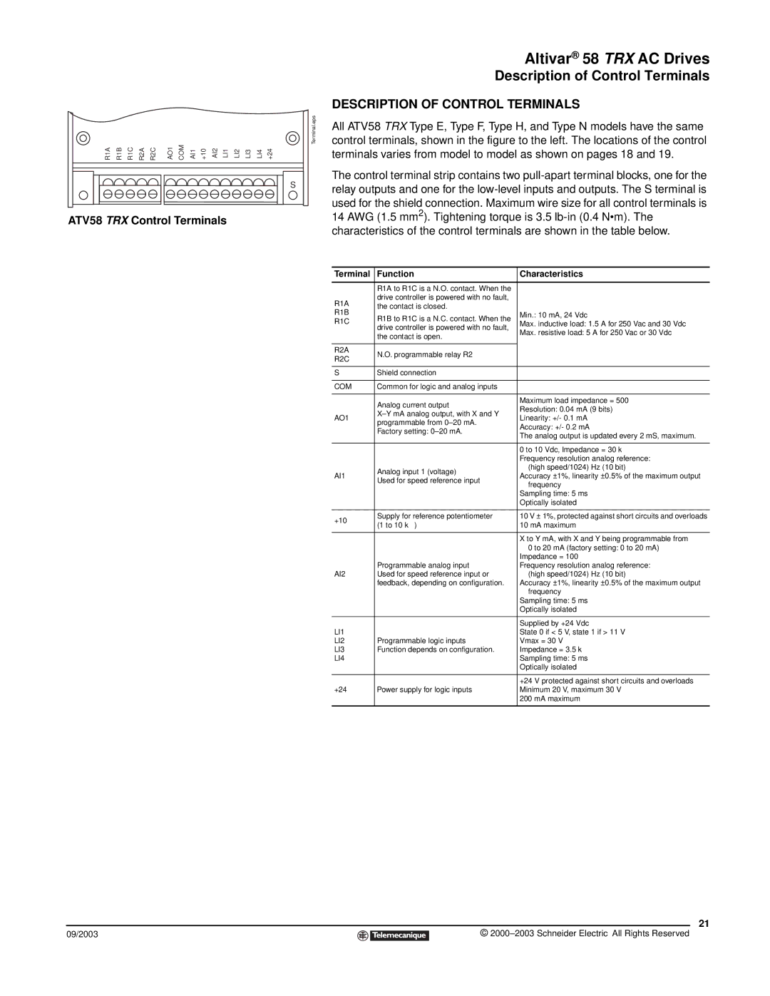
ATV58 TRX Control Terminals
Altivar® 58 TRX AC Drives
Description of Control Terminals
DESCRIPTION OF CONTROL TERMINALS
All ATV58 TRX Type E, Type F, Type H, and Type N models have the same control terminals, shown in the figure to the left. The locations of the control terminals varies from model to model as shown on pages 18 and 19.
The control terminal strip contains two
14AWG (1.5 mm2). Tightening torque is 3.5
Terminal | Function | Characteristics | |
|
|
| |
| R1A to R1C is a N.O. contact. When the |
| |
R1A | drive controller is powered with no fault, |
| |
the contact is closed. |
| ||
R1B |
| ||
R1B to R1C is a N.C. contact. When the | Min.: 10 mA, 24 Vdc | ||
R1C | |||
Max. inductive load: 1.5 A for 250 Vac and 30 Vdc | |||
drive controller is powered with no fault, | |||
| |||
| Max. resistive load: 5 A for 250 Vac or 30 Vdc | ||
| the contact is open. | ||
|
| ||
|
|
| |
R2A | N.O. programmable relay R2 |
| |
R2C |
| ||
|
| ||
|
|
| |
S | Shield connection |
| |
|
|
| |
COM | Common for logic and analog inputs |
| |
|
|
| |
| Analog current output | Maximum load impedance = 500 Ω | |
| Resolution: 0.04 mA (9 bits) | ||
| |||
AO1 | Linearity: +/- 0.1 mA | ||
programmable from | |||
| Accuracy: +/- 0.2 mA | ||
| Factory setting: | ||
| The analog output is updated every 2 mS, maximum. | ||
|
| ||
|
|
| |
|
| 0 to 10 Vdc, Impedance = 30 kΩ | |
|
| Frequency resolution analog reference: | |
| Analog input 1 (voltage) | (high speed/1024) Hz (10 bit) | |
AI1 | Accuracy ±1%, linearity ±0.5% of the maximum output | ||
Used for speed reference input | |||
| frequency | ||
|
| ||
|
| Sampling time: 5 ms | |
|
| Optically isolated | |
|
|
| |
+10 | Supply for reference potentiometer | 10 V ± 1%, protected against short circuits and overloads | |
(1 to 10 kΩ ) | 10 mA maximum | ||
| |||
|
|
| |
|
| X to Y mA, with X and Y being programmable from | |
|
| 0 to 20 mA (factory setting: 0 to 20 mA) | |
|
| Impedance = 100 Ω | |
| Programmable analog input | Frequency resolution analog reference: | |
AI2 | Used for speed reference input or | (high speed/1024) Hz (10 bit) | |
| feedback, depending on configuration. | Accuracy ±1%, linearity ±0.5% of the maximum output | |
|
| frequency | |
|
| Sampling time: 5 ms | |
|
| Optically isolated | |
|
|
| |
|
| Supplied by +24 Vdc | |
LI1 |
| State 0 if < 5 V, state 1 if > 11 V | |
LI2 | Programmable logic inputs | Vmax = 30 V | |
LI3 | Function depends on configuration. | Impedance = 3.5 kΩ | |
LI4 |
| Sampling time: 5 ms | |
|
| Optically isolated | |
|
|
| |
|
| +24 V protected against short circuits and overloads | |
+24 | Power supply for logic inputs | Minimum 20 V, maximum 30 V | |
|
| 200 mA maximum | |
|
|
|
21
09/2003 |
| © |
| ||
|
|
|