Altivar® 58 TRX AC Drives
Communication Parameters
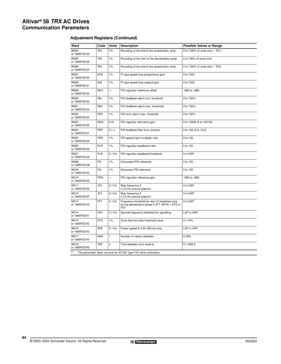
Adjustment Registers (Continued)
Word | Code | Units | Description | Possible Values or Range |
|
|
|
|
|
W294 | TA2 | 1% | Rounding of the end of the acceleration ramp | 0 to (100% of ramp time – TA1) |
or 16#5FE5/2D |
|
|
|
|
|
|
|
|
|
W295 | TA3 | 1% | Rounding of the start of the deceleration ramp | 0 to 100% of ramp time |
or 16#5FE5/2E |
|
|
|
|
|
|
|
|
|
W296 | TA4 | 1% | Rounding of the end of the deceleration ramp | 0 to (100% of ramp time – TA3) |
or 16#5FE5/2F |
|
|
|
|
|
|
|
|
|
W297 | SPG | 1% | PI type speed loop proportional gain | 0 to 1000 |
or 16#5FE5/30 |
|
|
|
|
|
|
|
|
|
W298 | SIG | 1% | PI type speed loop integral gain | 0 to 1000 |
or 16#5FE5/31 |
|
|
|
|
|
|
|
|
|
W299 | REO | — | PID regulator reference offset | |
or 16#5FE5/32 |
|
|
|
|
|
|
|
|
|
W300 | PAL | 1% | PID feedback alarm min. threshold | 0 to 100% |
or 16#5FE5/33 |
|
|
|
|
|
|
|
|
|
W301 | PAH | 1% | PID feedback alarm max. threshold | 0 to 100% |
or 16#5FE5/34 |
|
|
|
|
|
|
|
|
|
W302 | PER | 1% | PID error alarm max. threshold | 0 to 100% |
or 16#5FE5/35 |
|
|
|
|
|
|
|
|
|
W303 | RDG | 0.01 | PID regulator derivative gain | 0 to 10000 (0 to 100.00) |
or 16#5FE5/36 |
|
|
|
|
|
|
|
|
|
W304 | PSP | 0.1 s | PID feedback filter time constant | 0 to 100 (0 to 10.0) |
or 16#5FE5/37 |
|
|
|
|
|
|
|
|
|
W305 | PSR | 1% | PID speed input multiplier ratio | 0 to 100 |
or 16#5FE5/38 |
|
|
|
|
|
|
|
|
|
W306 | PLR | 1% | PID regulator deadband ratio | 0 to 100 |
or 16#5FE5/39 |
|
|
|
|
|
|
|
|
|
W307 | PLB | 0.1 Hz | PID regulator deadband threshold | 0 to HSP |
or 16#5FE5/3A |
|
|
|
|
|
|
|
|
|
W308 | PI2 | 1% | 2nd preset PID reference | 0 to 100 |
or 16#5FE5/3B |
|
|
|
|
|
|
|
|
|
W309 | PI3 | 1% | 3rd preset PID reference | 0 to 100 |
or 16#5FE5/3C |
|
|
|
|
|
|
|
|
|
W310 | PRG | — | PID regulator reference gain | |
or 16#5FE5/3D |
|
|
|
|
|
|
|
|
|
W311 | JF2 | 0.1 Hz | Skip frequency 2 | 0 to HSP |
or 16#5FE5/3E |
|
| ± 2.5 Hz around setpoint |
|
|
|
|
|
|
W312 | JF3 | 0.1 Hz | Skip frequency 3 | 0 to HSP |
or 16#5FE5/3F |
|
| ± 2.5 Hz around setpoint |
|
|
|
|
|
|
W313 | FFT | 0.1 Hz | Frequency threshold for start of freewheel stop | 0 to HSP |
or 16#5FE5/40 |
|
| during deceleration phase if STT (W79) = STN or |
|
|
|
| FST |
|
|
|
|
|
|
W314 | F2D | 0.1 Hz | Second frequency threshold for signalling | LSP to HSP |
or 16#5FE5/41 |
|
|
|
|
|
|
|
|
|
W315 | DTD | 1% | Drive thermal state threshold value | |
or 16#5FE5/42 |
|
|
|
|
|
|
|
|
|
W316 | SP8 | 0.1 Hz | Preset speed 8 | LSP to HSP |
or 16#5FE5/43 |
|
|
|
|
|
|
|
|
|
W317 | NAR | 1 | Number of restart attempts | |
or 16#5FE5/44 |
|
|
|
|
|
|
|
|
|
W318 | TAR | s | Time between auto restarts | |
or 16#5FE5/45 |
|
|
|
|
|
|
|
|
|
[1] This parameter does not exist for ATV58 Type FVC drive controllers.
84
© |
| 09/2003 |
| ||
|
|
|