Altivar® 58 TRX AC Drives
Description of Type FVC Control Terminals
DESCRIPTION OF ATV58 TYPE FVC CONTROL TERMINALS
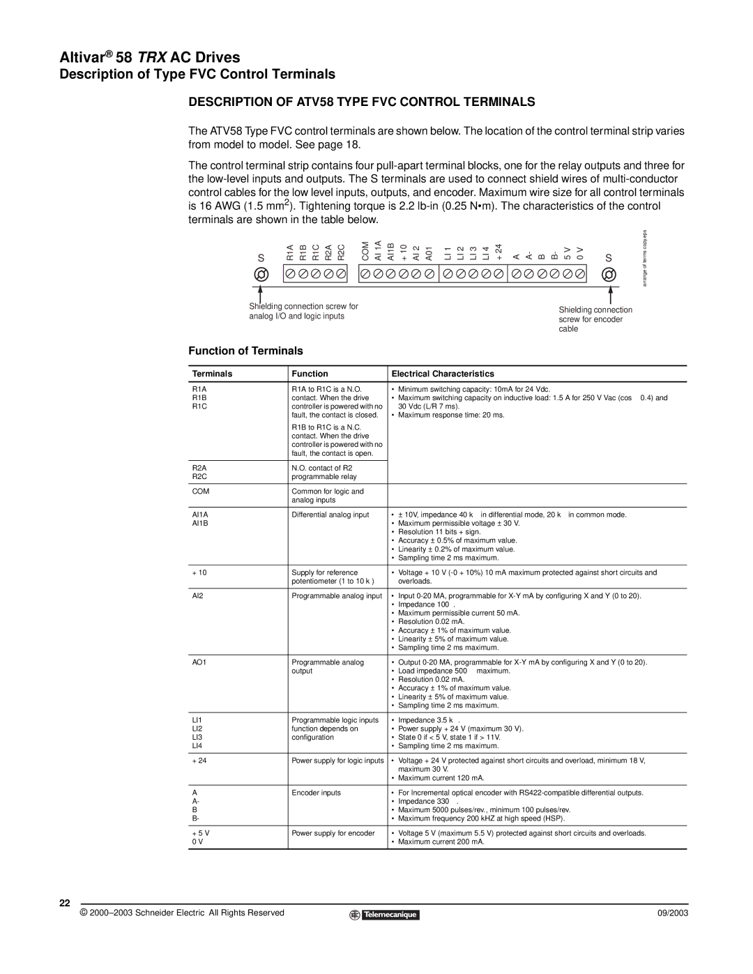
The ATV58 Type FVC control terminals are shown below. The location of the control terminal strip varies from model to model. See page 18.
The control terminal strip contains four
S
R1A | R1B | R1C | R2A | R2C | COM | AI 1A | AI1B | + 10 | AI 2 | A01 | LI 1 | LI 2 | LI 3 | LI 4 | + 24 | A | A- | B | B- | 5 V | 0 V |
|
|
|
|
|
|
|
|
|
|
|
|
|
|
|
|
|
|
|
|
|
|
|
|
|
|
|
|
|
|
|
|
|
|
|
|
|
|
|
|
|
|
|
|
S
arrange of terms copy.eps
Shielding connection screw for | Shielding connection | |
analog I/O and logic inputs | ||
screw for encoder | ||
| ||
| cable |
Function of Terminals
Terminals | Function | Electrical Characteristics | |
|
|
|
|
R1A | R1A to R1C is a N.O. | • | Minimum switching capacity: 10mA for 24 Vdc. |
R1B | contact. When the drive | • | Maximum switching capacity on inductive load: 1.5 A for 250 V Vac (cos ϕ 0.4) and |
R1C | controller is powered with no |
| 30 Vdc (L/R 7 ms). |
| fault, the contact is closed. | • | Maximum response time: 20 ms. |
| R1B to R1C is a N.C. |
|
|
| contact. When the drive |
|
|
| controller is powered with no |
|
|
| fault, the contact is open. |
|
|
|
|
|
|
R2A | N.O. contact of R2 |
|
|
R2C | programmable relay |
|
|
|
|
|
|
COM | Common for logic and |
|
|
| analog inputs |
|
|
|
|
|
|
AI1A | Differential analog input | • | ± 10V, impedance 40 k Ω in differential mode, 20 kΩ in common mode. |
AI1B |
| • | Maximum permissible voltage ± 30 V. |
|
| • | Resolution 11 bits + sign. |
|
| • | Accuracy ± 0.5% of maximum value. |
|
| • | Linearity ± 0.2% of maximum value. |
|
| • | Sampling time 2 ms maximum. |
|
|
|
|
+ 10 | Supply for reference | • | Voltage + 10 V |
| potentiometer (1 to 10 kΩ) |
| overloads. |
|
|
|
|
AI2 | Programmable analog input | • | Input |
|
| • | Impedance 100 Ω. |
|
| • | Maximum permissible current 50 mA. |
|
| • | Resolution 0.02 mA. |
|
| • | Accuracy ± 1% of maximum value. |
|
| • | Linearity ± 5% of maximum value. |
|
| • | Sampling time 2 ms maximum. |
|
|
|
|
AO1 | Programmable analog | • | Output |
| output | • | Load impedance 500 Ω maximum. |
|
| • | Resolution 0.02 mA. |
|
| • | Accuracy ± 1% of maximum value. |
|
| • | Linearity ± 5% of maximum value. |
|
| • | Sampling time 2 ms maximum. |
|
|
|
|
LI1 | Programmable logic inputs | • | Impedance 3.5 kΩ . |
LI2 | function depends on | • | Power supply + 24 V (maximum 30 V). |
LI3 | configuration | • | State 0 if < 5 V, state 1 if > 11V. |
LI4 |
| • | Sampling time 2 ms maximum. |
|
|
|
|
+ 24 | Power supply for logic inputs | • | Voltage + 24 V protected against short circuits and overload, minimum 18 V, |
|
|
| maximum 30 V. |
|
| • | Maximum current 120 mA. |
|
|
|
|
A | Encoder inputs | • | For Incremental optical encoder with |
A- |
| • | Impedance 330 Ω . |
B |
| • | Maximum 5000 pulses/rev., minimum 100 pulses/rev. |
B- |
| • | Maximum frequency 200 kHZ at high speed (HSP). |
|
|
|
|
+ 5 V | Power supply for encoder | • | Voltage 5 V (maximum 5.5 V) protected against short circuits and overloads. |
0 V |
| • Maximum current 200 mA. | |
|
|
|
|
22
© |
| 09/2003 |
| ||
|
|
|
