|
|
|
|
|
|
|
| Altivar® 58 TRX AC Drives | |
|
|
|
|
|
|
|
| Communication Parameters | |
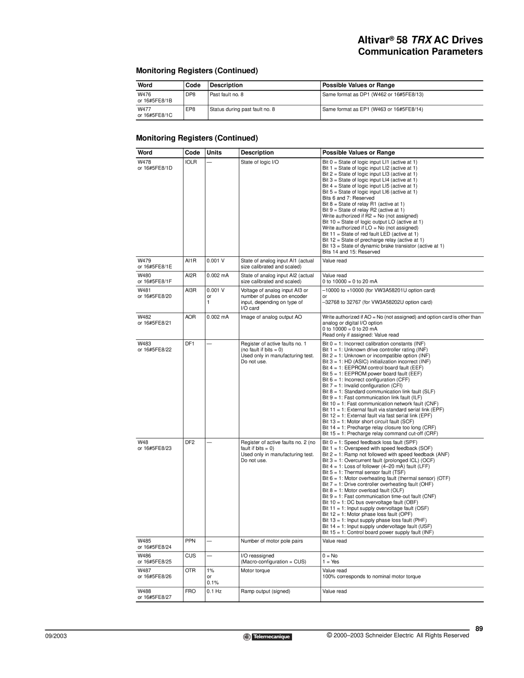
| Monitoring Registers (Continued) |
|
| ||||||
|
|
|
|
|
|
| |||
| Word | Code |
| Description | Possible Values or Range | ||||
|
|
|
|
|
|
| |||
| W476 | DP8 |
| Past fault no. 8 | Same format as DP1 (W462 or 16#5FE8/13) | ||||
| or 16#5FE8/1B |
|
|
|
|
|
|
|
|
|
|
|
|
|
|
| |||
| W477 | EP8 |
| Status during past fault no. 8 | Same format as EP1 (W463 or 16#5FE8/14) | ||||
| or 16#5FE8/1C |
|
|
|
|
|
|
|
|
|
|
|
|
|
|
|
| ||
| Monitoring Registers (Continued) |
|
| ||||||
|
|
|
|
|
| ||||
| Word | Code | Units | Description | Possible Values or Range | ||||
|
|
|
|
|
| ||||
| W478 | IOLR | — | State of logic I/O | Bit 0 = State of logic input LI1 (active at 1) | ||||
| or 16#5FE8/1D |
|
|
|
|
|
| Bit 1 = State of logic input LI2 (active at 1) | |
|
|
|
|
|
|
|
| Bit 2 = State of logic input LI3 (active at 1) | |
|
|
|
|
|
|
|
| Bit 3 = State of logic input LI4 (active at 1) | |
|
|
|
|
|
|
|
| Bit 4 = State of logic input LI5 (active at 1) | |
|
|
|
|
|
|
|
| Bit 5 = State of logic input LI6 (active at 1) | |
|
|
|
|
|
|
|
| Bits 6 and 7: Reserved | |
|
|
|
|
|
|
|
| Bit 8 = State of relay R1 (active at 1) | |
|
|
|
|
|
|
|
| Bit 9 = State of relay R2 (active at 1) | |
|
|
|
|
|
|
|
| Write authorized if R2 = No (not assigned) | |
|
|
|
|
|
|
|
| Bit 10 = State of logic output LO (active at 1) | |
|
|
|
|
|
|
|
| Write authorized if LO = No (not assigned) | |
|
|
|
|
|
|
|
| Bit 11 = State of red fault LED (active at 1) | |
|
|
|
|
|
|
|
| Bit 12 = State of precharge relay (active at 1) | |
|
|
|
|
|
|
|
| Bit 13 = State of dynamic brake transistor (active at 1) | |
|
|
|
|
|
|
|
| Bits 14 and 15: Reserved | |
|
|
|
|
|
| ||||
| W479 | AI1R | 0.001 V | State of analog input AI1 (actual | Value read | ||||
| or 16#5FE8/1E |
|
|
| size calibrated and scaled) |
|
| ||
|
|
|
|
|
| ||||
| W480 | AI2R | 0.002 mA | State of analog input AI2 (actual | Value read | ||||
| or 16#5FE8/1F |
|
|
| size calibrated and scaled) | 0 to 10000 = 0 to 20 mA | |||
|
|
|
|
|
| ||||
| W481 | AI3R | 0.001 V | Voltage of analog input AI3 or | |||||
| or 16#5FE8/20 |
| or | number of pulses on encoder | or | ||||
|
|
| 1 | input, depending on type of | |||||
|
|
|
|
| I/O card |
|
| ||
|
|
|
|
|
| ||||
| W482 | AOR | 0.002 mA | Image of analog output AO | Write authorized if AO = No (not assigned) and option card is other than | ||||
| or 16#5FE8/21 |
|
|
|
|
|
| analog or digital I/O option | |
|
|
|
|
|
|
|
| 0 to 10000 = 0 to 20 mA | |
|
|
|
|
|
|
|
| Read only if assigned: Value read | |
|
|
|
|
|
| ||||
| W483 | DF1 | — | Register of active faults no. 1 | Bit 0 = 1: Incorrect calibration constants (INF) | ||||
| or 16#5FE8/22 |
|
|
| (no fault if bits = 0) | Bit 1 = 1: Unknown drive controller rating (INF) | |||
|
|
|
|
| Used only in manufacturing test. | Bit 2 = 1: Unknown or incompatible option (INF) | |||
|
|
|
|
| Do not use. | Bit 3 = 1: HD (ASIC) initialization incorrect (INF) | |||
|
|
|
|
|
|
|
| Bit 4 = 1: EEPROM control board fault (EEF) | |
|
|
|
|
|
|
|
| Bit 5 = 1: EEPROM power board fault (EEF) | |
|
|
|
|
|
|
|
| Bit 6 = 1: Incorrect configuration (CFF) | |
|
|
|
|
|
|
|
| Bit 7 = 1: Invalid configuration (CFI) | |
|
|
|
|
|
|
|
| Bit 8 = 1: Standard communication link fault (SLF) | |
|
|
|
|
|
|
|
| Bit 9 = 1: Fast communication link fault (ILF) | |
|
|
|
|
|
|
|
| Bit 10 = 1: Fast communication network fault (CNF) | |
|
|
|
|
|
|
|
| Bit 11 = 1: External fault via standard serial link (EPF) | |
|
|
|
|
|
|
|
| Bit 12 = 1: External fault via fast serial link (EPF) | |
|
|
|
|
|
|
|
| Bit 13 = 1: Motor short circuit fault (SCF) | |
|
|
|
|
|
|
|
| Bit 14 = 1: Precharge relay closure too long (CRF) | |
|
|
|
|
|
|
|
| Bit 15 = 1: Precharge relay command | |
|
|
|
|
|
| ||||
| W48 | DF2 | — | Register of active faults no. 2 (no | Bit 0 = 1: Speed feedback loss fault (SPF) | ||||
| or 16#5FE8/23 |
|
|
| fault if bits = 0) | Bit 1 = 1: Overspeed with speed feedback (SOF) | |||
|
|
|
|
| Used only in manufacturing test. | Bit 2 = 1: Ramp not followed with speed feedback (ANF) | |||
|
|
|
|
| Do not use. | Bit 3 = 1: Overcurrent fault (prolonged ICL) (OCF) | |||
|
|
|
|
|
|
|
| Bit 4 = 1: Loss of follower | |
|
|
|
|
|
|
|
| Bit 5 = 1: Thermal sensor fault (TSF) | |
|
|
|
|
|
|
|
| Bit 6 = 1: Motor overheating fault (thermal sensor) (OTF) | |
|
|
|
|
|
|
|
| Bit 7 = 1: Drive controller overheating fault (OHF) | |
|
|
|
|
|
|
|
| Bit 8 = 1: Motor overload fault (OLF) | |
|
|
|
|
|
|
|
| Bit 9 = 1: Fast communication | |
|
|
|
|
|
|
|
| Bit 10 = 1: DC bus overvoltage fault (OBF) | |
|
|
|
|
|
|
|
| Bit 11 = 1: Input supply overvoltage fault (OSF) | |
|
|
|
|
|
|
|
| Bit 12 = 1: Motor phase loss fault (OPF) | |
|
|
|
|
|
|
|
| Bit 13 = 1: Input supply phase loss fault (PHF) | |
|
|
|
|
|
|
|
| Bit 14 = 1: Input supply undervoltage fault (USF) | |
|
|
|
|
|
|
|
| Bit 15 = 1: Control board power supply fault (INF) | |
|
|
|
|
|
| ||||
| W485 | PPN | — | Number of motor pole pairs | Value read | ||||
| or 16#5FE8/24 |
|
|
|
|
|
|
|
|
|
|
|
|
|
| ||||
| W486 | CUS | — | I/O reassigned | 0 = No | ||||
| or 16#5FE8/25 |
|
|
| 1 = Yes | ||||
|
|
|
|
|
| ||||
| W487 | OTR | 1% | Motor torque | Value read | ||||
| or 16#5FE8/26 |
| or |
|
|
| 100% corresponds to nominal motor torque | ||
|
|
| 0.1% |
|
|
|
|
| |
|
|
|
|
|
| ||||
| W488 | FRO | 0.1 Hz | Ramp output (signed) | Value read | ||||
| or 16#5FE8/27 |
|
|
|
|
|
|
|
|
|
|
|
|
|
|
|
|
|
|
|
|
|
|
|
|
|
|
| 89 |
09/2003 |
|
|
|
|
|
|
| © | |
|
|
|
|
|
| ||||
|
|
|
|
|
|
|
|
|
|