f (Hz) | SumInputs.eps |
| |
HSP |
|
LSP
t
AI2 or AI3
t
AI1
10 V
t
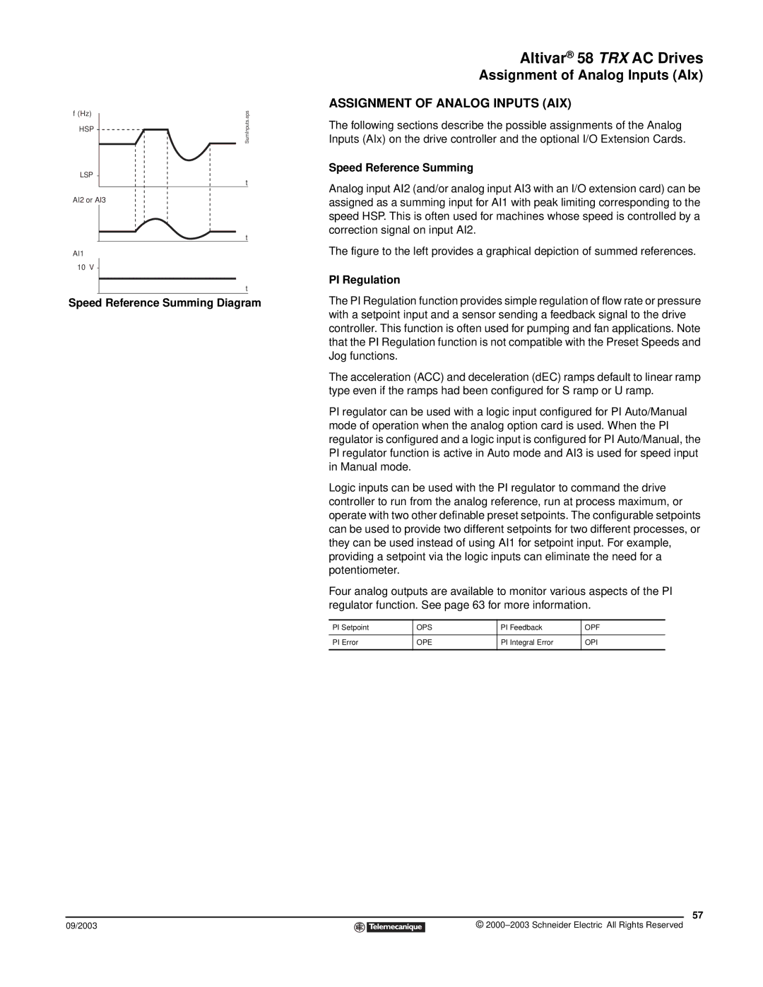
Speed Reference Summing Diagram
09/2003
Altivar® 58 TRX AC Drives
Assignment of Analog Inputs (AIx)
ASSIGNMENT OF ANALOG INPUTS (AIX)
The following sections describe the possible assignments of the Analog Inputs (AIx) on the drive controller and the optional I/O Extension Cards.
Speed Reference Summing
Analog input AI2 (and/or analog input AI3 with an I/O extension card) can be assigned as a summing input for AI1 with peak limiting corresponding to the speed HSP. This is often used for machines whose speed is controlled by a correction signal on input AI2.
The figure to the left provides a graphical depiction of summed references.
PI Regulation
The PI Regulation function provides simple regulation of flow rate or pressure with a setpoint input and a sensor sending a feedback signal to the drive controller. This function is often used for pumping and fan applications. Note that the PI Regulation function is not compatible with the Preset Speeds and Jog functions.
The acceleration (ACC) and deceleration (dEC) ramps default to linear ramp type even if the ramps had been configured for S ramp or U ramp.
PI regulator can be used with a logic input configured for PI Auto/Manual mode of operation when the analog option card is used. When the PI regulator is configured and a logic input is configured for PI Auto/Manual, the PI regulator function is active in Auto mode and AI3 is used for speed input in Manual mode.
Logic inputs can be used with the PI regulator to command the drive controller to run from the analog reference, run at process maximum, or operate with two other definable preset setpoints. The configurable setpoints can be used to provide two different setpoints for two different processes, or they can be used instead of using AI1 for setpoint input. For example, providing a setpoint via the logic inputs can eliminate the need for a potentiometer.
Four analog outputs are available to monitor various aspects of the PI regulator function. See page 63 for more information.
PI Setpoint | OPS | PI Feedback | OPF |
|
|
|
|
PI Error | OPE | PI Integral Error | OPI |
|
|
|
|
57
©