Altivar® 58 TRX AC Drives
Type FVC Specifications
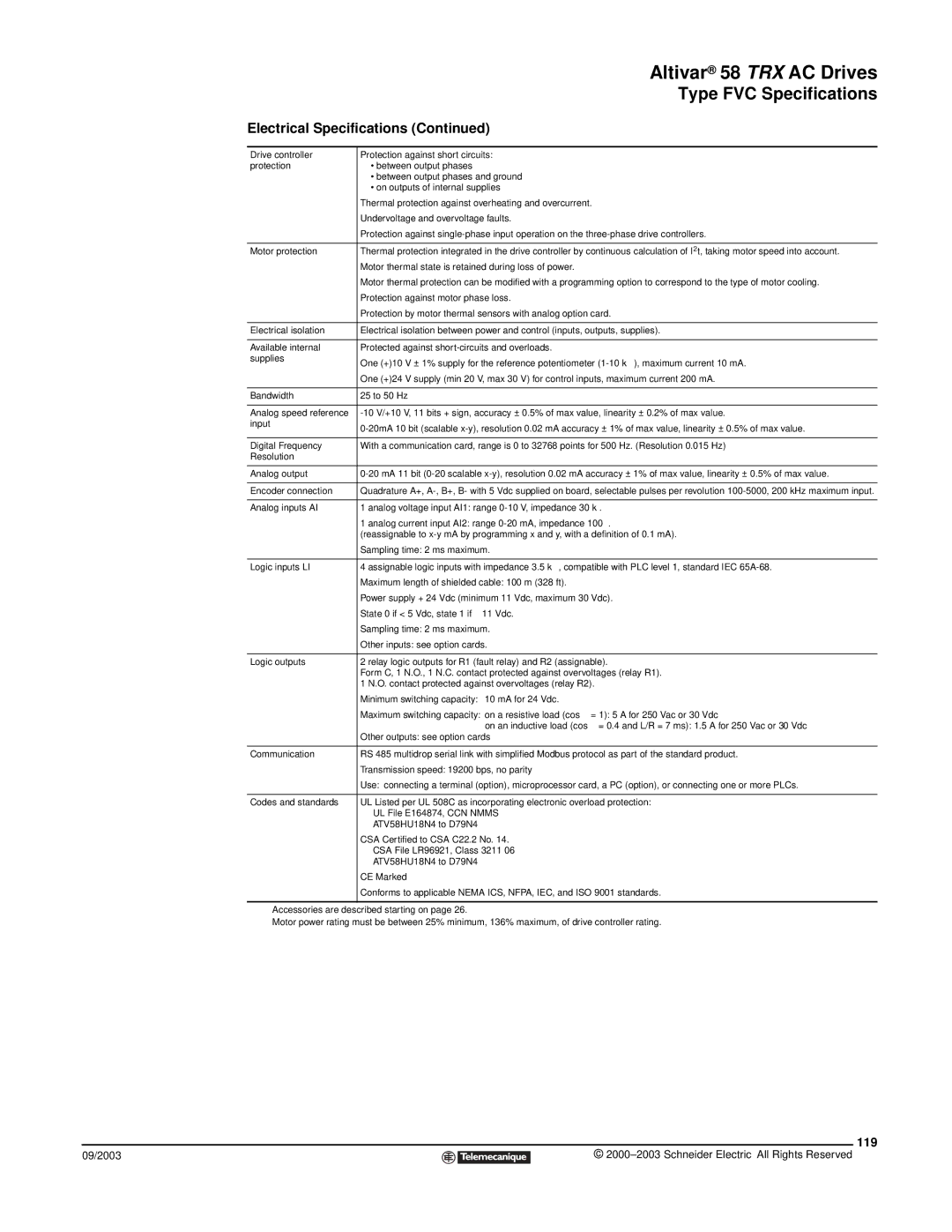
Electrical Specifications (Continued)
Drive controller | Protection against short circuits: |
protection | • between output phases |
| • between output phases and ground |
| • on outputs of internal supplies |
| Thermal protection against overheating and overcurrent. |
| Undervoltage and overvoltage faults. |
| Protection against |
|
|
Motor protection | Thermal protection integrated in the drive controller by continuous calculation of I2t, taking motor speed into account.■ |
| Motor thermal state is retained during loss of power. |
| Motor thermal protection can be modified with a programming option to correspond to the type of motor cooling.◆ |
| Protection against motor phase loss. |
| Protection by motor thermal sensors with analog option card.◆ |
Electrical isolation | Electrical isolation between power and control (inputs, outputs, supplies). |
|
|
Available internal | Protected against |
supplies | One (+)10 V ± 1% supply for the reference potentiometer |
| |
| One (+)24 V supply (min 20 V, max 30 V) for control inputs, maximum current 200 mA. |
|
|
Bandwidth | 25 to 50 Hz |
|
|
Analog speed reference | |
input | |
| |
|
|
Digital Frequency | With a communication card, range is 0 to 32768 points for 500 Hz. (Resolution 0.015 Hz) |
Resolution |
|
|
|
Analog output | |
|
|
Encoder connection | Quadrature A+, |
|
|
Analog inputs AI | 1 analog voltage input AI1: range |
| 1 analog current input AI2: range |
| (reassignable to |
| Sampling time: 2 ms maximum. |
|
|
Logic inputs LI | 4 assignable logic inputs with impedance 3.5 kΩ , compatible with PLC level 1, standard IEC |
| Maximum length of shielded cable: 100 m (328 ft). |
| Power supply + 24 Vdc (minimum 11 Vdc, maximum 30 Vdc). |
| State 0 if < 5 Vdc, state 1 if ≥ 11 Vdc. |
| Sampling time: 2 ms maximum. |
| Other inputs: see option cards. |
|
|
Logic outputs | 2 relay logic outputs for R1 (fault relay) and R2 (assignable). |
| Form C, 1 N.O., 1 N.C. contact protected against overvoltages (relay R1). |
| 1 N.O. contact protected against overvoltages (relay R2). |
| Minimum switching capacity: 10 mA for 24 Vdc. |
| Maximum switching capacity: on a resistive load (cos ϕ = 1): 5 A for 250 Vac or 30 Vdc |
| on an inductive load (cos ϕ = 0.4 and L/R = 7 ms): 1.5 A for 250 Vac or 30 Vdc |
| Other outputs: see option cards |
|
|
Communication | RS 485 multidrop serial link with simplified Modbus protocol as part of the standard product. |
| Transmission speed: 19200 bps, no parity |
| Use: connecting a terminal (option), microprocessor card, a PC (option), or connecting one or more PLCs. |
|
|
Codes and standards | UL Listed per UL 508C as incorporating electronic overload protection: |
| UL File E164874, CCN NMMS |
| ATV58HU18N4 to D79N4 |
| CSA Certified to CSA C22.2 No. 14. |
| CSA File LR96921, Class 3211 06 |
| ATV58HU18N4 to D79N4 |
| CE Marked |
| Conforms to applicable NEMA ICS, NFPA, IEC, and ISO 9001 standards. |
|
|
◆Accessories are described starting on page 26.
■Motor power rating must be between 25% minimum, 136% maximum, of drive controller rating.
119
09/2003 |
| © |
| ||
|
|
|