Altivar® 58 TRX AC Drives
Type H Specifications
[1]The maximum allowable input line unbalance is
5% for 460 V input line short circuit capacity of
15,000 A, 2.5% for 460 V input line short circuit capacity of 30,000 A, 0.5% for 460 V input line short circuit capacity of 65,000 A. If the resulting voltage harmonic distortion exceeds 5%, three phase line reactors are recommended.
[2]Input voltage is 460 V,
[3]See page 26 and following for available accessories and options.
[4]The drive controller can be configured to reduce switching frequency if the drive thermal state reaches 95%. When the drive thermal state returns to 70%, the switching frequency returns to the set value. If the duty cycle (drive controller run time) does not exceed 60% (36 second maximum for a 60 second cycle) derating is not required.
[5]Motor thermal protection can be set between 25 and 136% of the drive controller rating.
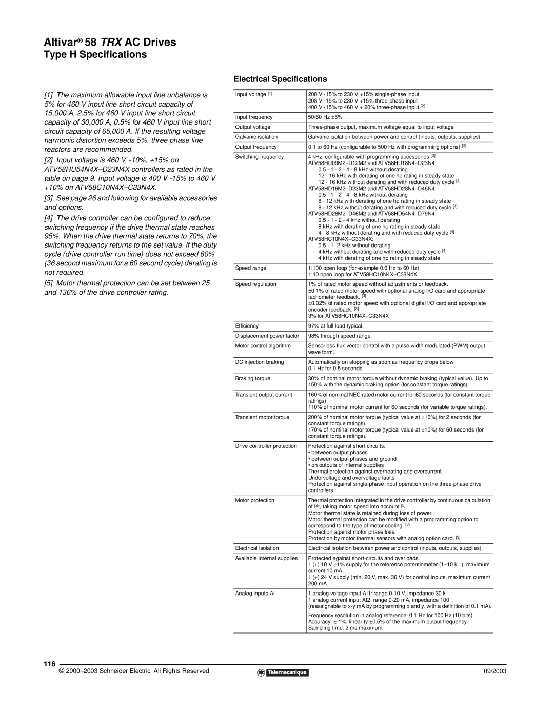
Electrical Specifications
Input voltage [1] | 208 V |
| 208 V |
| 400 V |
Input frequency | 50/60 Hz ±5% |
|
|
Output voltage | |
|
|
Galvanic isolation | Galvanic isolation between power and control (inputs, outputs, supplies) |
|
|
Output frequency | 0.1 to 60 Hz (configurable to 500 Hz with programming options) [3] |
Switching frequency | 4 kHz, configurable with programming accessories [3] |
| |
| 0.5 - 1 - 2 - 4 - 8 kHz without derating |
| 12 - 16 kHz with derating of one hp rating in steady state |
| 12 - 16 kHz without derating and with reduced duty cycle [4] |
| |
| 0.5 - 1 - 2 - 4 - 8 kHz without derating |
| 8 - 12 kHz with derating of one hp rating in steady state |
| 8 - 12 kHz without derating and with reduced duty cycle [4] |
| |
| 0.5 - 1 - 2 - 4 kHz without derating |
| 8 kHz with derating of one hp rating in steady state |
| 4 - 8 kHz without derating and with reduced duty cycle [4] |
| |
| 0.5 - 1- 2 kHz without derating |
| 4 kHz without derating and with reduced duty cycle [4] |
| 4 kHz with derating of one hp rating in steady state |
|
|
Speed range | 1:100 open loop (for example 0.6 Hz to 60 Hz) |
| 1:10 open loop for |
|
|
Speed regulation | 1% of rated motor speed without adjustments or feedback. |
| ±0.1% of rated motor speed with optional analog I/O card and appropriate |
| tachometer feedback. [3] |
| ±0.02% of rated motor speed with optional digital I/O card and appropriate |
| encoder feedback. [3] |
| 3% for |
|
|
Efficiency | 97% at full load typical. |
|
|
Displacement power factor | 98% through speed range. |
|
|
Motor control algorithm | Sensorless flux vector control with a pulse width modulated (PWM) output |
| wave form. |
|
|
DC injection braking | Automatically on stopping as soon as frequency drops below |
| 0.1 Hz for 0.5 seconds. |
|
|
Braking torque | 30% of nominal motor torque without dynamic braking (typical value). Up to |
| 150% with the dynamic braking option (for constant torque ratings). |
|
|
Transient output current | 160% of nominal NEC rated motor current for 60 seconds (for constant torque |
| ratings). |
| 110% of nominal motor current for 60 seconds (for variable torque ratings). |
|
|
Transient motor torque | 200% of nominal motor torque (typical value at ±10%) for 2 seconds (for |
| constant torque ratings). |
| 170% of nominal motor torque (typical value at ±10%) for 60 seconds (for |
| constant torque ratings). |
|
|
Drive controller protection | Protection against short circuits: |
| • between output phases |
| • between output phases and ground |
| • on outputs of internal supplies |
| Thermal protection against overheating and overcurrent. |
| Undervoltage and overvoltage faults. |
| Protection against |
| controllers. |
|
|
Motor protection | Thermal protection integrated in the drive controller by continuous calculation |
| of I2t, taking motor speed into account.[5] |
| Motor thermal state is retained during loss of power. |
| Motor thermal protection can be modified with a programming option to |
| correspond to the type of motor cooling. [3] |
| Protection against motor phase loss. |
| Protection by motor thermal sensors with analog option card. [3] |
Electrical isolation | Electrical isolation between power and control (inputs, outputs, supplies). |
|
|
Available internal supplies | Protected against |
| 1 (+) 10 V ±1% supply for the reference potentiometer |
| current 10 mA. |
| 1 (+) 24 V supply (min. 20 V, max. 30 V) for control inputs, maximum current |
| 200 mA. |
|
|
Analog inputs AI | 1 analog voltage input AI1: range |
| 1 analog current input AI2: range |
| (reassignable to |
| Frequency resolution in analog reference: 0.1 Hz for 100 Hz (10 bits). |
| Accuracy: ± 1%, linearity ±0.5% of the maximum output frequency. |
| Sampling time: 2 ms maximum. |
|
|
116
© |
| 09/2003 |
| ||
|
|
|