Altivar® 58 TRX AC Drives
Power Section Construction Information
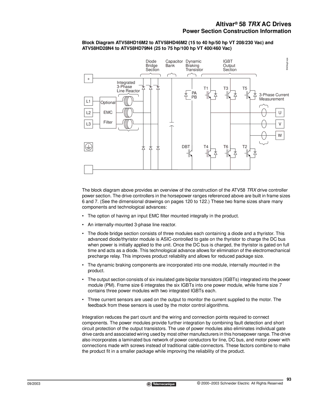
Block Diagram ATV58HD16M2 to ATV58HD46M2 (15 to 40 hp/50 hp VT 208/230 Vac) and ATV58HD28N4 to ATV58HD79N4 (25 to 75 hp/100 hp VT 400/460 Vac)
+
L1
L2 ![]()
L3 ![]()
Optional
EMC
Filter
Diode | Capacitor | Dynamic | IGBT | BlkDiag2.eps |
Bridge | Bank | Braking | Output |
|
Section |
| Transistor | Section |
|
Integrated |
|
|
|
|
| T1 | T3 | T5 | |
Line Reactor |
| |||
| PA |
| ||
|
|
| ||
|
| PB |
| |
|
|
| Measurement | |
|
|
|
| |
|
|
|
| U |
|
|
|
| V |
|
|
|
| W |
DBT T4 T6 T2
−
The block diagram above provides an overview of the construction of the ATV58 TRX drive controller power section. The drive controllers in the horsepower ranges referenced above are built in frame sizes 6 and 7. (See the dimensional drawings on pages 120 to 122.) These two frame sizes share many components and technological advances:
•The option of having an input EMC filter mounted integrally in the product.
•An
•The diode bridge section consists of three modules each containing a diode and a thyristor. This advanced diode/thyristor module is
•The dynamic braking components are incorporated into one module, internally mounted in the product.
•The output section consists of six insulated gate bipolar transistors (IGBTs) integrated into the power module (PM). Frame size 6 integrates the six IGBTs into one power module, while frame size 7 contains three power modules with two integrated IGBTs each.
•Three current sensors are used on the output to monitor the current supplied to the motor. The feedback from these sensors is used by the motor control algorithms.
Integration reduces the part count and the wiring and connection points required to connect components. The power modules provide further integration by combining fault detection and short circuit protection of the output transistors. The use of power modules also eliminates individual gate drive cards and associated wiring used by most other manufacturers in this horsepower range. The drive also incorporates a laminated bus network of power conductors for line, DC bus, and motor power with connections made with screws instead of traditional cable connectors. These factors combine to make the product fit in a smaller package while improving the reliability of the product.
93
09/2003 |
| © |
| ||
|
|
|