Altivar® 58 TRX AC Drives
Communication Parameters
NOTE: Refer to bulletin VVDED397058US for specific address numbers and more information.
COMMUNICATION PARAMETERS
(PARAMETERS AVAILABLE VIA THE COMMUNICATION LINK)
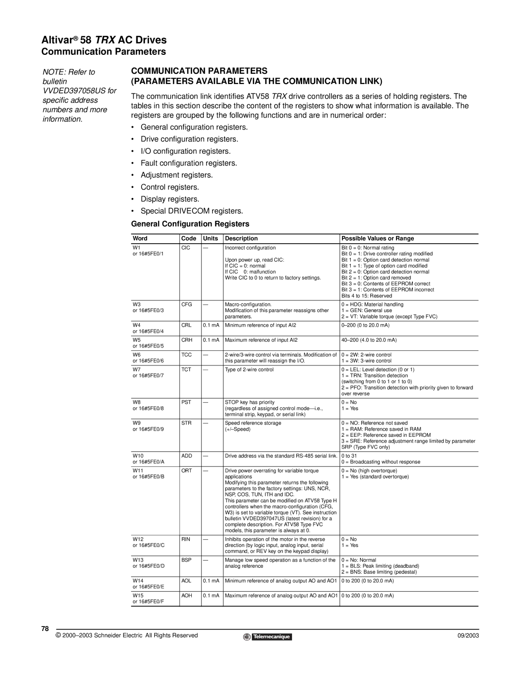
The communication link identifies ATV58 TRX drive controllers as a series of holding registers. The tables in this section describe the content of the registers to show what information is available. The registers are grouped by the following functions and are in numerical order:
•General configuration registers.
•Drive configuration registers.
•I/O configuration registers.
•Fault configuration registers.
•Adjustment registers.
•Control registers.
•Display registers.
•Special DRIVECOM registers.
General Configuration Registers
Word | Code | Units | Description | Possible Values or Range | |
|
|
|
|
| |
W1 | CIC | — | Incorrect configuration | Bit 0 = 0: Normal rating | |
or 16#5FE0/1 |
|
|
| Bit 0 = 1: Drive controller rating modified | |
|
|
| Upon power up, read CIC: | Bit 1 = 0: Option card detection normal | |
|
|
| If CIC = 0: normal | Bit 1 = 1: Type of option card modified | |
|
|
| If CIC ≠ 0: malfunction | Bit 2 = 0: Option card detection normal | |
|
|
| Write CIC to 0 to return to factory settings. | Bit 2 = 1: Option card removed | |
|
|
|
| Bit 3 = 0: Contents of EEPROM correct | |
|
|
|
| Bit 3 = 1: Contents of EEPROM incorrect | |
|
|
|
| Bits 4 to 15: Reserved | |
|
|
|
|
|
|
W3 | CFG | — | 0 | = HDG: Material handling | |
or 16#5FE0/3 |
|
| Modification of this parameter reassigns other | 1 | = GEN: General use |
|
|
| parameters. | 2 | = VT: Variable torque (except Type FVC) |
|
|
|
|
| |
W4 | CRL | 0.1 mA | Minimum reference of input AI2 | ||
or 16#5FE0/4 |
|
|
|
|
|
|
|
|
|
| |
W5 | CRH | 0.1 mA | Maximum reference of input AI2 | ||
or 16#5FE0/5 |
|
|
|
|
|
|
|
|
|
|
|
W6 | TCC | — | 0 | = 2W: | |
or 16#5FE0/6 |
|
| this parameter will reassign the I/O. | 1 | = 3W: |
|
|
|
|
| |
W7 | TCT | — | Type of | 0 = LEL: Level detection (0 or 1) | |
or 16#5FE0/7 |
|
|
| 1 | = TRN: Transition detection |
|
|
|
| (switching from 0 to 1 or 1 to 0) | |
|
|
|
| 2 | = PFO: Transition detection with priority given to forward |
|
|
|
| over reverse | |
|
|
|
|
|
|
W8 | PST | — | STOP key has priority | 0 | = No |
or 16#5FE0/8 |
|
| (regardless of assigned control | 1 | = Yes |
|
|
| terminal strip, keypad, or serial link) |
|
|
|
|
|
|
|
|
W9 | STR | — | Speed reference storage | 0 | = NO: Reference not saved |
or 16#5FE0/9 |
|
| 1 | = RAM: Reference saved in RAM | |
|
|
|
| 2 | = EEP: Reference saved in EEPROM |
|
|
|
| 3 | = SRE: Reference adjustment range limited by parameter |
|
|
|
| SRP (Type FVC only) | |
|
|
|
|
| |
W10 | ADD | — | Drive address via the standard | 0 to 31 | |
or 16#5FE0/A |
|
|
| 0 | = Broadcasting without response |
|
|
|
|
|
|
W11 | ORT | — | Drive power overrating for variable torque | 0 | = No (high overtorque) |
or 16#5FE0/B |
|
| applications | 1 | = Yes (standard overtorque) |
|
|
| Modifying this parameter returns the following |
|
|
|
|
| parameters to the factory settings: UNS, NCR, |
|
|
|
|
| NSP, COS, TUN, ITH and IDC. |
|
|
|
|
| This parameter can be modified on ATV58 Type H |
|
|
|
|
| controllers when the |
|
|
|
|
| W3) is set to variable torque (VT). See instruction |
|
|
|
|
| bulletin VVDED397047US (latest revision) for a |
|
|
|
|
| complete description. For ATV58 Type FVC |
|
|
|
|
| models, this parameter is always at 0. |
|
|
|
|
|
|
|
|
W12 | RIN | — | Inhibits operation of the motor in the reverse | 0 | = No |
or 16#5FE0/C |
|
| direction (by logic input, analog input, serial | 1 | = Yes |
|
|
| command, or REV key on the keypad display) |
|
|
|
|
|
|
|
|
W13 | BSP | — | Manage low speed operation as a function of the | 0 | = No: Normal |
or 16#5FE0/D |
|
| analog reference | 1 | = BLS: Peak limiting (deadband) |
|
|
|
| 2 | = BNS: Base limiting (pedestal) |
|
|
|
|
| |
W14 | AOL | 0.1 mA | Minimum reference of analog output AO and AO1 | 0 to 200 (0 to 20.0 mA) | |
or 16#5FE0/E |
|
|
|
|
|
|
|
|
|
| |
W15 | AOH | 0.1 mA | Maximum reference of analog output AO and AO1 | 0 to 200 (0 to 20.0 mA) | |
or 16#5FE0/F |
|
|
|
|
|
|
|
|
|
|
|
78
© |
| 09/2003 |
| ||
|
|
|