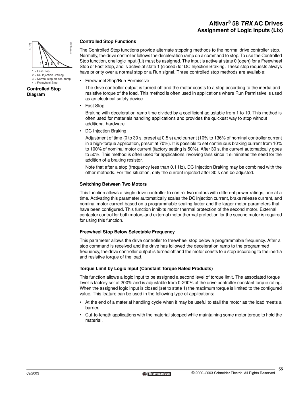
f (Hz) | CntrlStop.eps |
1 2 3 4
1 = Fast Stop
2 = DC Injection Braking
3 = Normal stop on dec. ramp
4 = Freewheel Stop
Controlled Stop
Diagram
09/2003
Altivar® 58 TRX AC Drives
Assignment of Logic Inputs (LIx)
Controlled Stop Functions
The Controlled Stop functions provide alternate stopping methods to the normal drive controller stop. Normally, the drive controller follows the deceleration ramp on a command to stop. To use the Controlled Stop function, one logic input (LI) must be assigned. The input is active at state 0 (open) for a Freewheel Stop or Fast Stop, and is active at state 1 (closed) for DC Injection Braking. These stop requests always have priority over a normal stop or a Run signal. Three controlled stop methods are available:
•Freewheel Stop/Run Permissive
The drive controller output is turned off and the motor coasts to a stop according to the inertia and resistive torque of the load. This method is often used in applications where Run Permissive is used as an electrical safety device.
•Fast Stop
Braking with deceleration ramp time divided by a coefficient adjustable from 1 to 10. This method is often used for materials handling applications and provides the quickest way to stop without additional hardware.
•DC Injection Braking
Adjustment of time (0 to 30 s, preset at 0.5 s) and current (10% to 136% of nominal controller current in a
Note that after a stop (frequency less than 0.1 Hz), DC Injection Braking may be combined with the other methods. For this situation, only the current injected after 30 s can be adjusted.
Switching Between Two Motors
This function allows a single drive controller to control two motors with different power ratings, one at a time. Activating this parameter automatically scales the DC injection current, brake release current, and nominal motor current based on a programmable scaling factor and the larger motor parameters that have been configured. This function inhibits motor thermal protection of the second motor. External contactor control for both motors and external motor thermal protection for the second motor is required for using this function.
Freewheel Stop Below Selectable Frequency
This parameter allows the drive controller to freewheel stop below a programmable frequency. After a stop command is received and the drive has followed the deceleration ramp to the programmed frequency, the drive controller output is turned off and the motor coasts to a stop according to the inertia and resistive torque of the load.
Torque Limit by Logic Input (Constant Torque Rated Products)
This function allows a logic input to be assigned a second level of torque limit. The associated torque level is factory set at 200% and is adjustable from
•At the end of a material handling cycle when it may be useful to stall the motor as the load meets a barrier.
•
55
©