Altivar® 58 TRX AC Drives
Communication Parameters
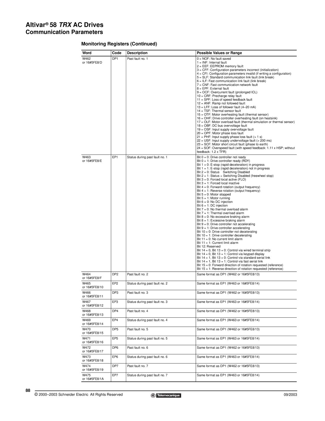
Monitoring Registers (Continued)
Word | Code | Description | Possible Values or Range |
|
|
|
|
W462 | DP1 | Past fault no. 1 | 0 = NOF: No fault saved |
or 16#5FE8/D |
|
| 1 = INF: Internal fault |
|
|
| 2 = EEF: EEPROM memory fault |
|
|
| 3 = CFF: Configuration parameters incorrect (initialization) |
|
|
| 4 = CFI: Configuration parameters invalid (if writing a configuration) |
|
|
| 5 = SLF: Standard communication link fault (link break) |
|
|
| 6 = ILF: Fast communication link fault (link break) |
|
|
| 7 = CNF: Fast communication network fault |
|
|
| 8 = EPF: External fault |
|
|
| 9 = OCF: Overcurrent fault (prolonged ICL) |
|
|
| 10 = CRF: Precharge relay fault |
|
|
| 11 = SPF: Loss of speed feedback fault |
|
|
| 12 = ANF: Ramp not followed fault |
|
|
| 13 = LFF: Loss of follower fault |
|
|
| 14 = TSF: Thermal sensor fault |
|
|
| 15 = OTF: Motor overheating fault (thermal sensor) |
|
|
| 16 = OHF: Drive controller overheating fault (on heatsink) |
|
|
| 17 = OLF: Motor overload fault (thermal simulation or thermal sensor) |
|
|
| 18 = OBF: DC bus overvoltage fault |
|
|
| 19 = OSF: Input supply overvoltage fault |
|
|
| 20 = OPF: Motor phase loss fault |
|
|
| 21 = PHF: Input supply phase loss fault (> 1 s) |
|
|
| 22 = USF: Input supply undervoltage fault (> 200 ms) |
|
|
| 23 = SCF: Motor short circuit fault (phase to earth) |
|
|
| 24 = SOF: Overspeed fault (with speed feedback: 1.11 x HSP; without |
|
|
| feedback: 1.2 x TFR) |
|
|
|
|
W463 | EP1 | Status during past fault no. 1 | Bit 0 = 0: Drive controller not ready |
or 16#5FE8/E |
|
| Bit 0 = 1: Drive controller ready (RDY) |
|
|
| Bit 1 = 0: |
|
|
| Bit 1 = 1: |
|
|
| Bit 2 = 0: Status ≠ Switching Disabled |
|
|
| Bit 2 = 1: Status = Switching Disabled (freewheel stop) |
|
|
| Bit 3 = 0: Forced local active (FLO) |
|
|
| Bit 3 = 1: Forced local inactive |
|
|
| Bit 4 = 0: Forward rotation (output frequency) |
|
|
| Bit 4 = 1: Reverse rotation (output frequency) |
|
|
| Bit 5 = 0: Motor stopped |
|
|
| Bit 5 = 1: Motor running |
|
|
| Bit 6 = 0: No DC injection |
|
|
| Bit 6 = 1: DC injection |
|
|
| Bit 7 = 0: No thermal overload alarm |
|
|
| Bit 7 = 1: Thermal overload alarm |
|
|
| Bit 8 = 0: No excessive braking alarm |
|
|
| Bit 8 = 1: Excessive braking alarm |
|
|
| Bit 9 = 0: Drive controller not accelerating |
|
|
| Bit 9 = 1: Drive controller accelerating |
|
|
| Bit 10 = 0: Drive controller not decelerating |
|
|
| Bit 10 = 1: Drive controller decelerating |
|
|
| Bit 11 = 0: No current limit alarm |
|
|
| Bit 11 = 1: Current limit alarm |
|
|
| Bit 12: Reserved |
|
|
| Bit 14 = 0, Bit 13 = 0: Control via wired terminal strip |
|
|
| Bit 14 = 0, Bit 13 = 1: Control via keypad display |
|
|
| Bit 14 = 1, Bit 13 = 0: Control via standard serial link |
|
|
| Bit 14 = 1, Bit 13 = 1: Control via fast serial link |
|
|
| Bit 15 = 0: Forward direction of rotation requested (reference) |
|
|
| Bit 15 = 1: Reverse direction of rotation requested (reference) |
|
|
|
|
W464 | DP2 | Past fault no. 2 | Same format as DP1 (W462 or 16#5FE8/13) |
or 16#5FE8/F |
|
|
|
|
|
|
|
W465 | EP2 | Status during past fault no. 2 | Same format as EP1 (W463 or 16#5FE8/14) |
or 16#5FE8/10 |
|
|
|
|
|
|
|
W466 | DP3 | Past fault no. 3 | Same format as DP1 (W462 or 16#5FE8/13) |
or 16#5FE8/11 |
|
|
|
|
|
|
|
W467 | EP3 | Status during past fault no. 3 | Same format as EP1 (W463 or 16#5FE8/14) |
or 16#5FE8/12 |
|
|
|
|
|
|
|
W468 | DP4 | Past fault no. 4 | Same format as DP1 (W462 or 16#5FE8/13) |
or 16#5FE8/13 |
|
|
|
|
|
|
|
W469 | EP4 | Status during past fault no. 4 | Same format as EP1 (W463 or 16#5FE8/14) |
or 16#5FE8/14 |
|
|
|
|
|
|
|
W470 | DP5 | Past fault no. 5 | Same format as DP1 (W462 or 16#5FE8/13) |
or 16#5FE8/15 |
|
|
|
|
|
|
|
W471 | EP5 | Status during past fault no. 5 | Same format as EP1 (W463 or 16#5FE8/14) |
or 16#5FE8/16 |
|
|
|
|
|
|
|
W472 | DP6 | Past fault no. 6 | Same format as DP1 (W462 or 16#5FE8/13) |
or 16#5FE8/17 |
|
|
|
|
|
|
|
W473 | EP6 | Status during past fault no. 6 | Same format as EP1 (W463 or 16#5FE8/14) |
or 16#5FE8/18 |
|
|
|
|
|
|
|
W474 | DP7 | Past fault no. 7 | Same format as DP1 (W462 or 16#5FE8/13) |
or 16#5FE8/19 |
|
|
|
|
|
|
|
W475 | EP7 | Status during past fault no. 7 | Same format as EP1 (W463 or 16#5FE8/14) |
or 16#5FE8/1A |
|
|
|
|
|
|
|
88
© |
| 09/2003 |
| ||
|
|
|