Altivar® 58 TRX AC Drives
Wiring Recommendations
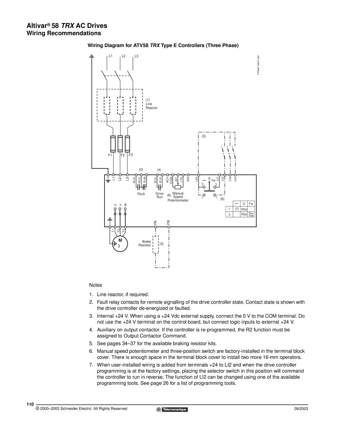
Wiring Diagram for ATV58 TRX Type E Controllers (Three Phase)
L1 L2 L3
(1) Line Reactor
(3)
3 Phase Type E.eps
F1
F2 F3
(2) (4)
L1 | L2 |
| L3 | R1A | R1C | R1B | K13 |
| K14 | AO1 COM |
| AI1 | +10 |
| AI2 | +24 | ||||||||||
|
|
|
|
|
|
|
|
|
|
|
|
|
|
|
|
|
|
|
|
|
|
|
|
| ||
|
|
|
|
|
|
|
|
|
|
|
|
|
|
|
|
|
|
|
| Manual |
|
| ||||
|
|
|
|
|
|
|
|
|
|
| Fault | Drive | (6) |
|
| |||||||||||
|
|
|
|
|
|
|
|
|
|
|
|
|
|
|
| Run | Speed |
|
| |||||||
|
|
|
|
|
|
|
|
|
|
|
|
|
|
|
|
|
|
| Potentiometer |
| ||||||
| U |
| V | W |
|
|
|
|
|
|
|
|
|
|
|
|
|
|
|
|
| |||||
|
|
|
|
|
|
|
|
|
|
|
|
|
|
|
|
|
|
|
|
|
|
|
|
|
|
|
|
|
|
|
|
|
|
|
|
|
|
|
|
|
|
|
|
|
|
|
|
|
|
|
|
|
|
|
|
|
| 0 Fw LI1 | |||
3 |
|
| |||||
|
| 3 | |||||
|
|
|
|
|
|
|
|
|
|
|
|
|
|
|
|
1 1
LI2 | LI3 | LI4 |
(6)
|
|
|
| O | Fw |
|
|
|
| ||
1 | [7] | Stop |
| ||
|
|
|
|
|
|
3 |
|
|
| Stop | Run |
|
|
|
|
| Fwd |
|
| PA | PB |
T1 | T2 | T3 |
|
| M | Brake | (5) |
| 3φ | Resistor | |
|
|
Notes
1.Line reactor, if required.
2.Fault relay contacts for remote signalling of the drive controller state. Contact state is shown with the drive controller
3.Internal +24 V. When using a +24 Vdc external supply, connect the 0 V to the COM terminal. Do not use the +24 V terminal on the control board, but connect logic inputs to external +24 V.
4.Auxiliary on output contactor. If the controller is
5.See pages
6.Manual speed potentiometer and
7.When
110
© |
| 09/2003 |
| ||
|
|
|