Control terminal strip
AO1 | COM | AI1 | +10V | AI2 | LI1 | LI2 | LI3 | LI4 | +24V | wiring.eps |
|
|
|
|
|
|
|
|
|
| input |
| Top of the logic |
|
|
|
|
|
|
| ||
| input module |
|
|
|
|
|
|
| ||
|
|
|
|
|
| NOTE: 115 Vac is |
|
| ||
Module |
|
|
|
|
| present at these five |
| |||
terminal block |
|
|
|
|
| terminals. |
|
|
| |
DC control wiring |
|
| AC control wiring |
|
| |||||
AO1 | COM | AI1 | +10V | AI2 | ACI1 ACI2 ACI3 ACI4 ACCOM |
| ||||
|
|
|
|
|
| SW2 | SW3 | SW4 |
|
|
|
|
|
|
|
|
|
| ~ 115 V | ||
|
|
|
|
| SW1 |
|
|
|
|
|
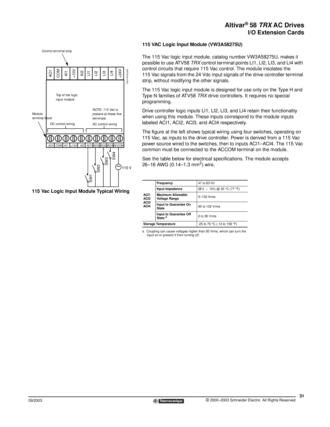
115 Vac Logic Input Module Typical Wiring
09/2003
Altivar® 58 TRX AC Drives
I/O Extension Cards
115 VAC Logic Input Module (VW3A58275U)
The 115 Vac logic input module, catalog number VW3A58275U, makes it possible to use ATV58 TRX control terminal points LI1, LI2, LI3, and LI4 with control circuits that require 115 Vac control. The module insolates the
115 Vac signals from the 24 Vdc input signals of the drive controller terminal strip, without modifying the other signals.
The 115 Vac logic input module is designed for use only on the Type H and Type N families of ATV58 TRX drive controllers. It requires no special programming.
Drive controller logic inputs LI1, LI2, LI3, and LI4 retain their functionality when using this module. These inputs correspond to the module inputs labeled ACI1, ACI2, ACI3, and ACI4 respectively.
The figure at the left shows typical wiring using four switches, operating on 115 Vac, as inputs to the drive controller. Power is derived from a 115 Vac power source wired to the switches, then to inputs ACI1–ACI4. The 115 Vac common must be connected to the ACCOM terminal on the module.
See the table below for electrical specifications. The module accepts
| Frequency | 47 to 63 Hz | |
|
|
| |
| Input Impedance | 28 kΩ ± 10% @ 25 °C (77 °F) | |
|
|
| |
ACI1 | Maximum Allowable | ||
ACI2 | Voltage Range | ||
| |||
ACI3 |
|
| |
Input to Guarantee On |
| ||
ACI4 | 90 to 132 Vrms | ||
State | |||
|
| ||
|
|
| |
| Input to Guarantee Off | 0 to 50 Vrms | |
| State a | ||
Storage Temperature | |||
|
|
| |
a.Coupling can cause voltages higher than 50 Vrms, which can turn the input on or prevent it from turning off.
31
©