Altivar® 58 TRX AC Drives
Display Parameters
DISPLAY PARAMETERS
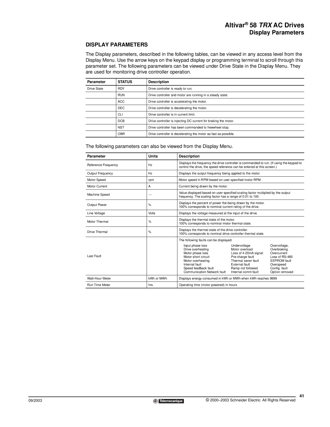
The Display parameters, described in the following tables, can be viewed in any access level from the Display Menu. Use the arrow keys on the keypad display or programming terminal to scroll through this parameter set. The following parameters can be viewed under Drive State in the Display Menu. They are used for monitoring drive controller operation.
Parameter | STATUS | Description |
|
|
|
Drive State | RDY | Drive controller is ready to run. |
|
|
|
| RUN | Drive controller and motor are running in a steady state. |
|
|
|
| ACC | Drive controller is accelerating the motor. |
|
|
|
| DEC | Drive controller is decelerating the motor. |
|
|
|
| CLI | Drive controller is in current limit. |
|
|
|
| DCB | Drive controller is injecting DC current for braking the motor. |
|
|
|
| NST | Drive controller has been commanded to freewheel stop. |
|
|
|
| OBR | Drive controller is decelerating the motor as fast as possible. |
|
|
|
The following parameters can also be viewed from the Display Menu.
Parameter | Units | Description |
|
| |
|
|
| |||
Reference Frequency | Hz | Displays the frequency the drive controller is commanded to run. (If using the keypad to | |||
control the drive, the speed reference can be entered at this screen.) | |||||
|
| ||||
|
|
|
| ||
Output Frequency | Hz | Displays the output frequency being applied to the motor. |
| ||
|
|
|
| ||
Motor Speed | rpm | Motor speed in RPM based on user specified motor RPM. |
| ||
|
|
|
|
| |
Motor Current | A | Current being drawn by the motor. |
|
| |
|
|
| |||
Machine Speed | Value displayed based on user specified scaling factor multiplied by the output | ||||
frequency. The scaling factor has a range of 0.01 to 100. |
| ||||
|
|
| |||
|
|
|
| ||
Output Power | % | Displays the percent of power the being drawn by the motor. |
| ||
100% corresponds to nominal current rating of the drive. |
| ||||
|
|
| |||
|
|
|
| ||
Line Voltage | Volts | Displays the voltage measured at the input of the drive. |
| ||
|
|
|
| ||
Motor Thermal | % | Displays the thermal state of the motor. |
| ||
100% corresponds to nominal motor thermal state. |
| ||||
|
|
| |||
|
|
|
| ||
Drive Thermal | % | Displays the thermal state of the drive controller. |
| ||
100% corresponds to nominal drive controller thermal state. |
| ||||
|
|
| |||
|
|
|
| ||
|
| The following faults can be displayed: |
| ||
|
| Input phase loss | Undervoltage | Overvoltage, | |
|
| Drive overheating | Motor overload | Overbraking | |
Last Fault |
| Motor phase loss | Loss of | Overcurrent | |
| Motor short circuit | Loss of | |||
|
| Motor overheating | Thermal senor fault | EEPROM fault | |
|
| Internal fault | External fault | Overspeed | |
|
| Speed feedback fault | Ramp not followed | Config. fault | |
|
| Communication Network fault | Internal comm fault | Option removed | |
|
|
| |||
kWh or MWh | Displays energy consumed in kWh or MWh when kWh reaches 9999 | ||||
|
|
|
| ||
Run Time Meter | hrs | Operating time (motor powered) in hours |
| ||
|
|
|
|
| |
41
09/2003 |
| © |
| ||
|
|
|