Altivar® 58 TRX AC Drives
Dynamic Braking Resistor Kits
DYNAMIC BRAKING RESISTOR KITS
The dynamic braking resistor kit allows the ATV58 TRX drive controllers to function in quadrants 2 and 4 of the four quadrant speed/torque curve. In these quadrants of motor operation, the motor is essentially a generator through which energy is transferred from the motor load back to the drive controller. This results in elevated DC bus voltage to the drive controller which may cause it to shutdown to protect itself. Dynamic braking resistor kits are commonly used to dissipate the excess energy generated by the motor operating in this mode. The flow of current to the braking resistor is controlled by the dynamic braking transistor (see the block diagrams on page
The following table shows the minimum ohmic value of the resistor that can be used with the
ATV58 TRX drive controllers. Using lower than recommended values will cause excessive current flow, exceeding the rating of the dynamic braking transistor.
Minimum Ohmic Value of Resistors
Which Can Be Used with ATV58 TRX Controllers
Model (ATV58) | Minimum Resistance Value in Ohms | Model (ATV58) | Minimum Resistance Value in Ohms | |
|
|
|
| |
|
| U18N4 |
| |
U09M2 | 75 | U29N4 | 85 | |
U18M2 | U41N4 | |||
|
| |||
|
| U54N4 |
| |
|
|
|
| |
U29M2 | 38 | U72N4 | 57 | |
U41M2 | ||||
|
|
| ||
|
|
|
| |
U54M2 | 31 | U90N4 | 47 | |
|
|
|
| |
U72M2 | 25 | D12N4 | 53 | |
|
|
|
| |
U72M2 | 13 | D16N4 | 19 | |
D12M2 | D23N4 | |||
|
| |||
|
|
|
| |
D16M2X | 8 | D28N4, D28N4X |
| |
|
| D33N4, D33N4X | 14 | |
D23M2X | 8 | |||
D46N4, D46N4X |
| |||
|
|
|
| |
D28M2X | 4 | D54N4, D54N4X | 8 | |
|
|
|
| |
D33M2X | 2.67 | D64N4, D64N4X | 5 | |
|
| |||
D46M2X | 2.67 | D79N4, D79N4X | ||
| ||||
|
| |||
|
|
|
|
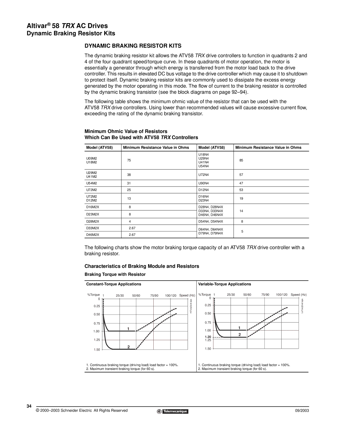
The following charts show the motor braking torque capacity of an ATV58 TRX drive controller with a braking resistor.
Characteristics of Braking Module and Resistors
Braking Torque with Resistor
%Torque 1 | 25/30 | 50/60 | 75/90 | 100/120 Speed (Hz) | |||
0 |
|
|
|
|
|
| HiTorqGraf.eps |
|
|
|
|
|
| ||
0.25 |
|
|
|
|
|
| |
|
|
|
|
|
|
| |
0.50 |
|
|
|
|
|
|
|
|
|
|
|
|
|
| |
0.75
Variable-Torque Applications
%Torque 1 | 25/30 | 50/60 | 75/90 | 100/120 Speed (Hz) | |||
0 |
|
|
|
|
|
| LoTorqGraf.eps |
|
|
|
|
|
| ||
0.25 |
|
|
|
|
|
| |
|
|
|
|
|
|
| |
0.50 |
|
|
|
|
|
|
|
|
|
|
|
|
|
| |
0.75
1.00
1
1.00
1
1.20
2
1.25
2
1.50
1.25
1.50
1.Continuous braking torque (driving load) load factor = 100%.
2.Maximum transient braking torque (for 60 s).
1.Continuous braking torque (driving load) load factor = 100%.
2.Maximum transient braking torque (for 60 s).
34
© |
| 09/2003 |
| ||
|
|
|
