I | limit | FanLoad.eps |
100 % CLI |
| |
| Cold air |
|
50 % CLI |
|
|
| Hot air |
|
|
| f/fn |
0 | 0.5 | 1 HSP |
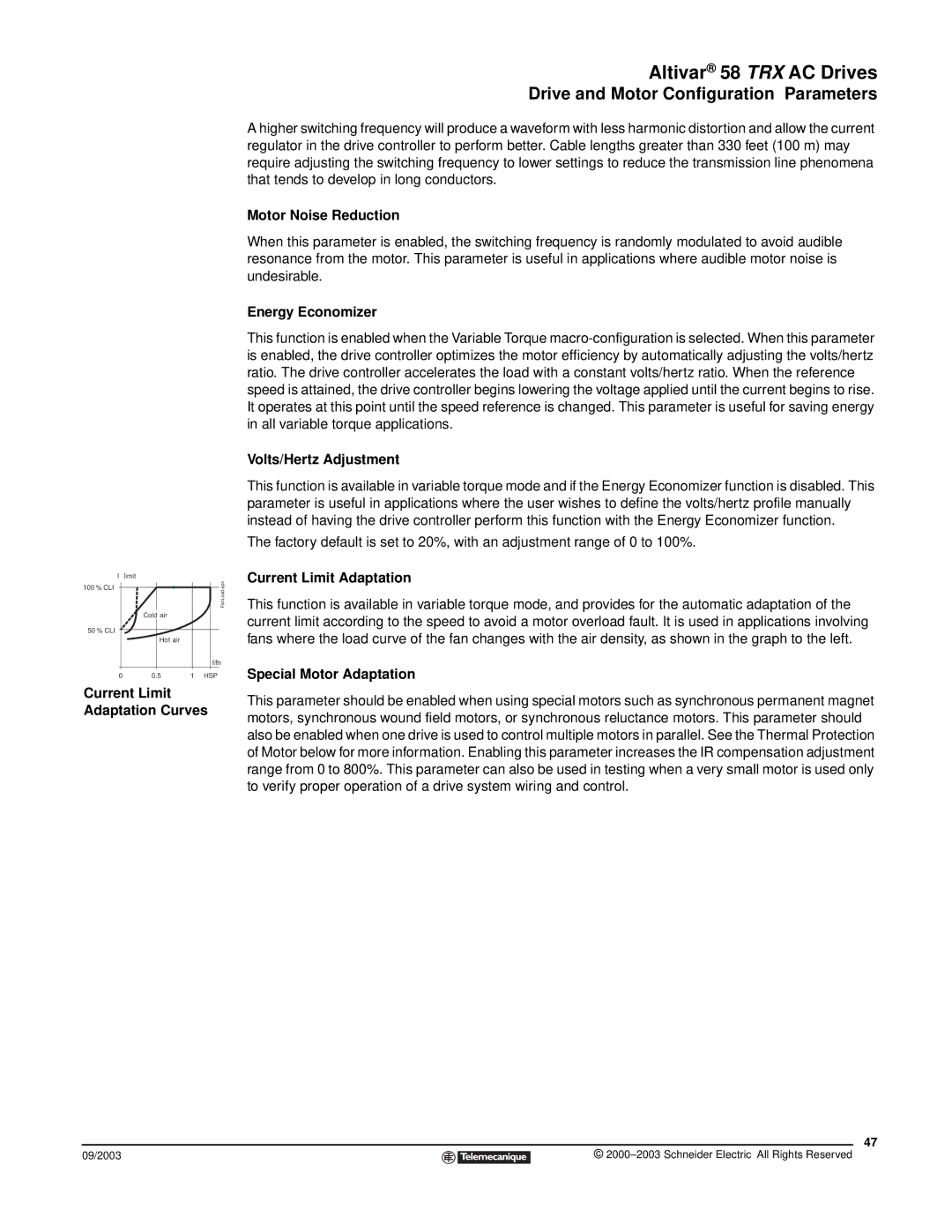
Current Limit Adaptation Curves
09/2003
Altivar® 58 TRX AC Drives
Drive and Motor Configuration Parameters
A higher switching frequency will produce a waveform with less harmonic distortion and allow the current regulator in the drive controller to perform better. Cable lengths greater than 330 feet (100 m) may require adjusting the switching frequency to lower settings to reduce the transmission line phenomena that tends to develop in long conductors.
Motor Noise Reduction
When this parameter is enabled, the switching frequency is randomly modulated to avoid audible resonance from the motor. This parameter is useful in applications where audible motor noise is undesirable.
Energy Economizer
This function is enabled when the Variable Torque
Volts/Hertz Adjustment
This function is available in variable torque mode and if the Energy Economizer function is disabled. This parameter is useful in applications where the user wishes to define the volts/hertz profile manually instead of having the drive controller perform this function with the Energy Economizer function.
The factory default is set to 20%, with an adjustment range of 0 to 100%.
Current Limit Adaptation
This function is available in variable torque mode, and provides for the automatic adaptation of the current limit according to the speed to avoid a motor overload fault. It is used in applications involving fans where the load curve of the fan changes with the air density, as shown in the graph to the left.
Special Motor Adaptation
This parameter should be enabled when using special motors such as synchronous permanent magnet motors, synchronous wound field motors, or synchronous reluctance motors. This parameter should also be enabled when one drive is used to control multiple motors in parallel. See the Thermal Protection of Motor below for more information. Enabling this parameter increases the IR compensation adjustment range from 0 to 800%. This parameter can also be used in testing when a very small motor is used only to verify proper operation of a drive system wiring and control.
47
©