Class 8839 58M Enclosed AC Drives
Dimensions and Weights for Mounting
hp | 460 V VT | 125 | 150– | 125 | 150– | ||
200 | 200 | ||||||
|
|
|
|
| |||
|
|
|
|
|
|
| |
Weight |
| lb | 1025 | 1175 | 1150 | 1300 | |
|
|
|
|
|
| ||
| kg | 464.9 | 532.9 | 521.6 | 589.6 | ||
|
| ||||||
|
|
|
|
|
|
| |
| C | in. | 5.84 | 10.63 | 5.84 | 10.63 | |
|
|
|
|
|
| ||
| mm | 148.3 | 270.0 | 148.3 | 270.0 | ||
|
| ||||||
|
|
|
|
|
|
| |
Dimensions | D | in. | 25 | 30 | 25 | 30 | |
|
|
|
|
| |||
mm | 635 | 762 | 635 | 762 | |||
| |||||||
|
|
|
|
|
| ||
E | in. | 22.2 | 27.2 | 22.2 | 27.2 | ||
|
|
|
|
| |||
mm |
|
|
|
| |||
Enclosure |
| 563.8 | 690.8 | 563.8 | 690.8 | ||
|
|
|
|
|
| ||
F | in. | 22.5 | 25.0 | 25.0 | 27.5 | ||
|
|
|
|
| |||
mm | 571.5 | 635 | 635 | 698.5 | |||
| |||||||
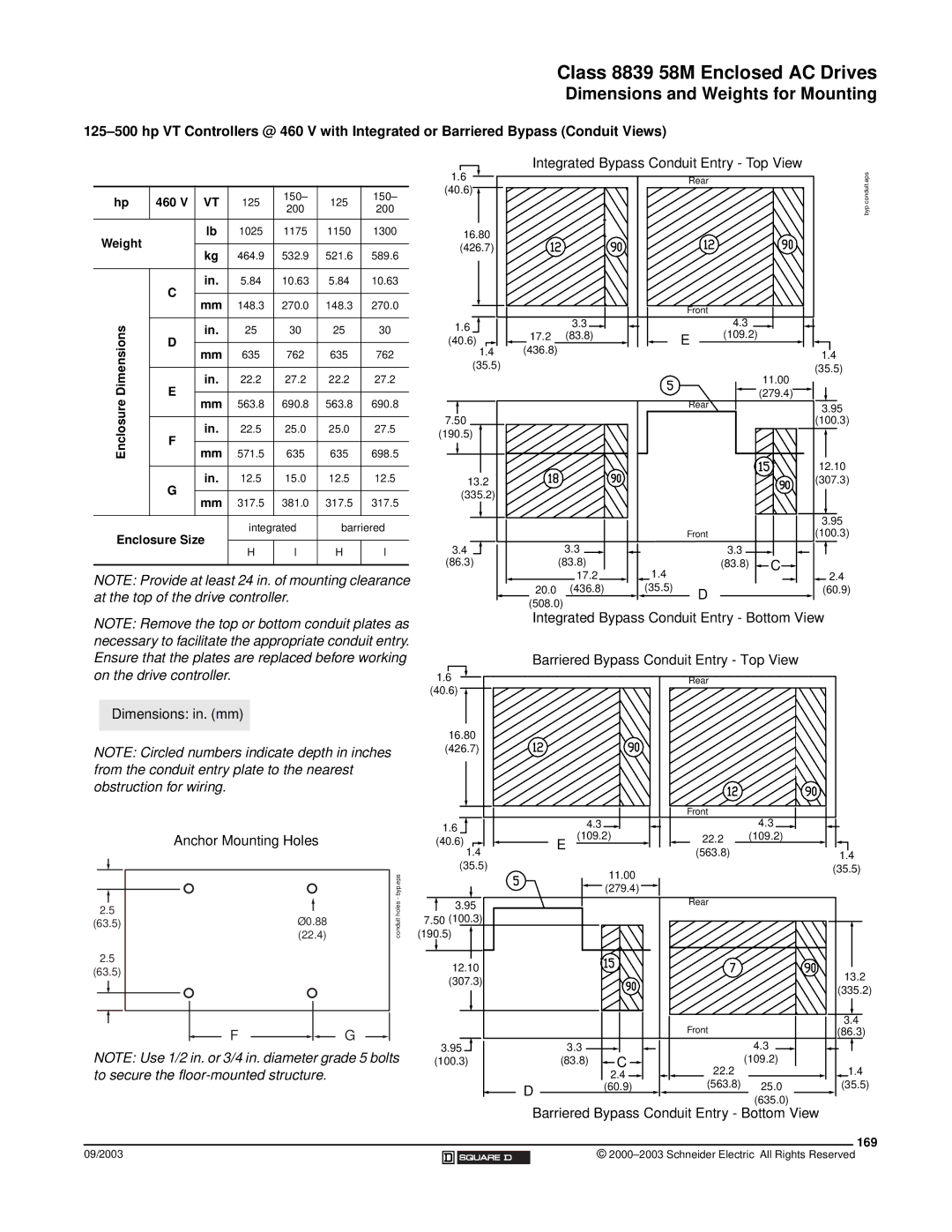
Integrated Bypass Conduit Entry - Top View
1.6 | Rear | |
(40.6) | ||
|
16.80
(426.7)
|
| Front |
| |
1.6 | 3.3 |
| 4.3 | |
17.2 (83.8) | E | (109.2) | ||
(40.6) | ||||
| ||||
1.4 | (436.8) |
| 1.4 | |
(35.5) |
|
| ||
|
| (35.5) | ||
|
|
| ||
|
|
| 11.00 | |
|
|
| (279.4) | |
|
| Rear | 3.95 | |
|
|
| ||
7.50 |
|
| (100.3) | |
(190.5) |
|
|
| |
|
|
| 12.10 |
byp conduit.eps
G | in. | 12.5 | 15.0 | 12.5 | 12.5 | |
|
|
|
|
| ||
mm | 317.5 | 381.0 | 317.5 | 317.5 | ||
| ||||||
|
|
|
| |||
Enclosure Size | integrated | barriered | ||||
|
|
|
| |||
H | I | H | I | |||
|
| |||||
|
|
|
|
|
| |
NOTE: Provide at least 24 in. of mounting clearance at the top of the drive controller.
13.2
(335.2)
3.4![]()
(86.3)
3.3 ![]()
(83.8)
17.2
20.0(436.8)
(508.0)
|
| (307.3) |
|
| 3.95 |
| Front | (100.3) |
| 3.3 |
|
1.4 | (83.8) | C |
| 2.4 | |
(35.5) | D | (60.9) |
|
|
NOTE: Remove the top or bottom conduit plates as necessary to facilitate the appropriate conduit entry. Ensure that the plates are replaced before working on the drive controller.
Integrated Bypass Conduit Entry - Bottom View
Barriered Bypass Conduit Entry - Top View
1.6 ![]()
![]() Rear
Rear
(40.6)
Dimensions: in. (mm)
NOTE: Circled numbers indicate depth in inches from the conduit entry plate to the nearest obstruction for wiring.
16.80
(426.7)
|
|
|
| Anchor Mounting Holes |
| ||
|
|
|
|
|
|
| holes - byp.eps |
|
|
|
|
|
|
| |
|
|
|
|
|
|
| |
|
|
|
|
|
|
| |
|
|
|
|
| |||
|
|
|
|
|
| ||
2.5 |
|
|
|
| |||
| Ø0.88 | ||||||
(63.5) |
| conduit | |||||
|
|
|
| (22.4) | |||
|
|
|
|
| |||
2.5
1.6 | 4.3 | |
(109.2) | ||
(40.6) | ||
E | ||
1.4 |
| |
(35.5) | 11.00 | |
| ||
| (279.4) |
3.95
7.50(100.3)
(190.5)
Front
4.3
22.2 (109.2)
(563.8)1.4
(35.5)
Rear
(63.5)
F ![]()
![]() G
G
NOTE: Use 1/2 in. or 3/4 in. diameter grade 5 bolts to secure the
12.10
(307.3)
|
|
|
|
|
|
|
|
|
|
|
|
3.95 |
| 3.3 |
|
|
|
|
|
|
| ||
|
|
|
|
|
|
|
| ||||
|
|
|
|
|
|
|
| ||||
(100.3) | (83.8) |
|
|
|
| C | |||||
|
| ||||||||||
|
|
|
|
|
|
| 2.4 | ||||
D(60.9)
Front
4.3
(109.2)
22.2
(563.8) 25.0
(635.0)
13.2
(335.2)
3.4
(86.3)
1.4
(35.5)
09/2003
Barriered Bypass Conduit Entry - Bottom View
169
©