Altivar® 58 TRX AC Drives
Installation Recommendations
Calculating Enclosure Size
The equation for calculating Rth (°C/W), the maximum allowable thermal resistance of the enclosure, is:
Rth = Ti – To
P
Ti = Max. internal ambient temp. (°C) around drive controller
To = Max. external temp. (°C) around enclosure P = Total power dissipated in enclosure (W)
Useful heat exchange surface area, S (in2), of a
NOTE: Contact enclosure manufacturer for K factors.
K | R t h = | Thermal resistance of the enclosure (calculated previously) |
S = | K = | Thermal resistance per square inch of the enclosure. |
Rth |
Consider the following points when sizing the enclosure:
•Use only metallic enclosures since they have good thermal conduction.
•This procedure does not consider radiant or convected heat load from external sources. Do not install enclosures where external heat sources (such as direct sunlight) can add to enclosure heat load.
•If additional devices are present inside the enclosure, consider the heat load of the devices in the calculation.
•The actual useful area for convection cooling of the enclosure will vary depending upon the method of mounting. The method of mounting must allow for free air movement over all surfaces considered for convection cooling.
The following example illustrates calculation of the enclosure size for an ATV58HU29N4 (2 HP) drive controller mounted in a Type 12 enclosure.
•Maximum external temperature: To = 25 °C
•Power dissipated inside enclosure: P = 97 W (from ratings tables; see page 10)
•Maximum internal temperature: Ti = 40 °C
•Thermal resistance per square inch of enclosure: K = 186
•Calculate maximum allowable thermal resistance, Rth:
40 °C – 25 °C
Rth =
97 W
• Calculate minimum useful heat exchange surface area, S:
1862 S =
0.16
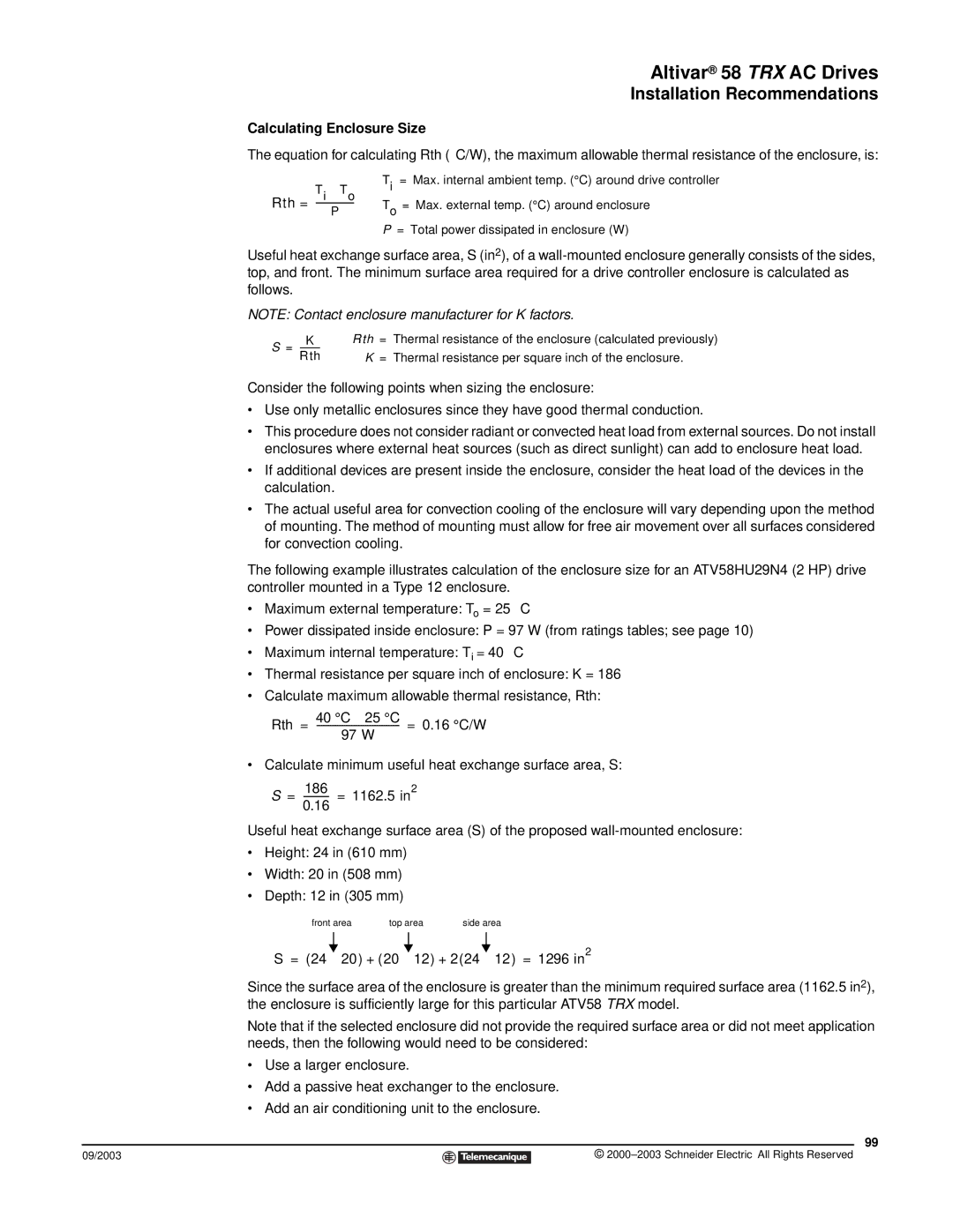
Useful heat exchange surface area (S) of the proposed
•Height: 24 in (610 mm)
•Width: 20 in (508 mm)
•Depth: 12 in (305 mm)
front area top area side area
S = (24 ⋅![]() 20) + (20 ⋅
20) + (20 ⋅ ![]() 12) + 2(24 ⋅
12) + 2(24 ⋅![]() 12) = 1296 in2
12) = 1296 in2
Since the surface area of the enclosure is greater than the minimum required surface area (1162.5 in2), the enclosure is sufficiently large for this particular ATV58 TRX model.
Note that if the selected enclosure did not provide the required surface area or did not meet application needs, then the following would need to be considered:
•Use a larger enclosure.
•Add a passive heat exchanger to the enclosure.
•Add an air conditioning unit to the enclosure.
99
09/2003 |
| © |
| ||
|
|
|
