h | Clearances.eps |
|
dd
h
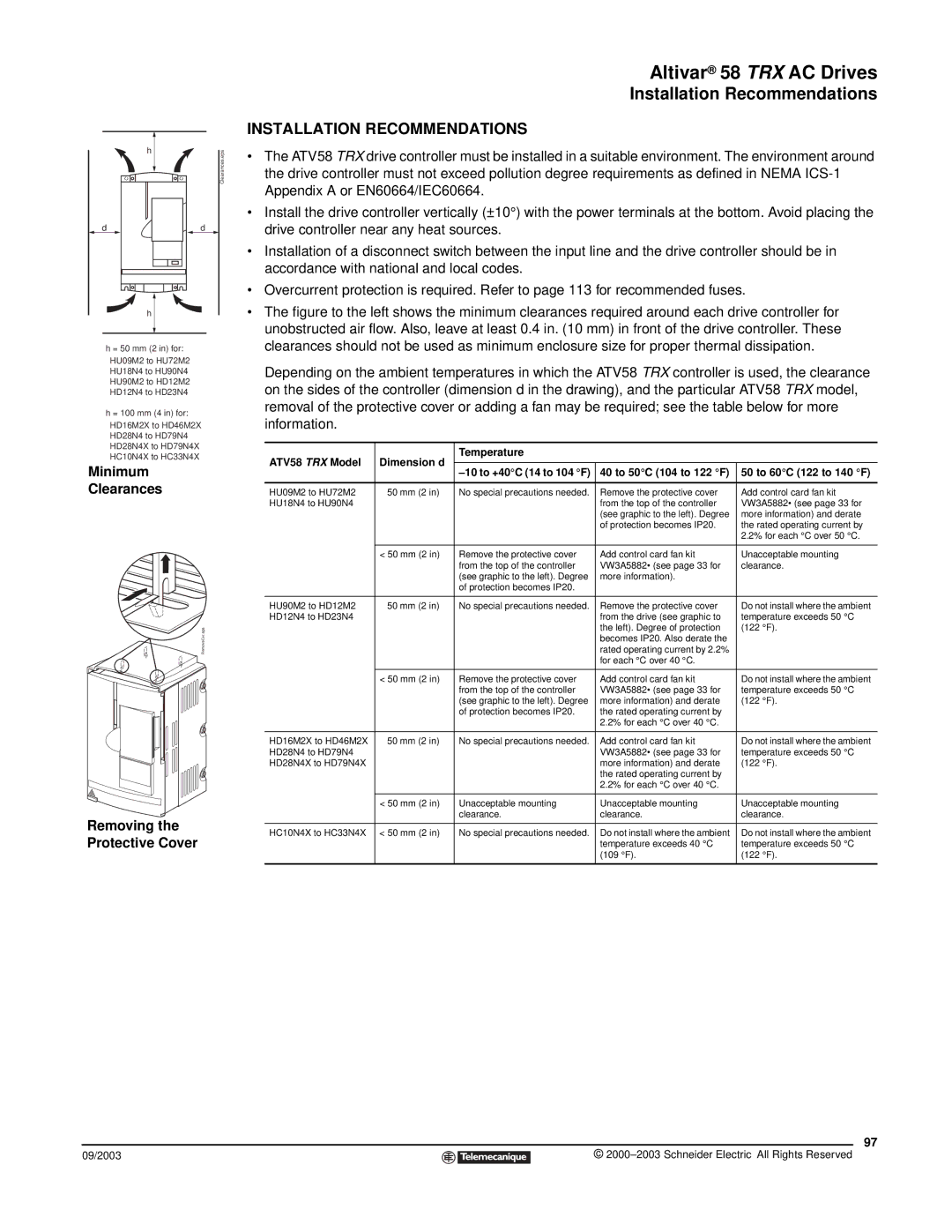
h = 50 mm (2 in) for: HU09M2 to HU72M2 HU18N4 to HU90N4 HU90M2 to HD12M2 HD12N4 to HD23N4
h = 100 mm (4 in) for: HD16M2X to HD46M2X HD28N4 to HD79N4 HD28N4X to HD79N4X HC10N4X to HC33N4X
Minimum
Clearances
RemoveCvr.eps
Removing the Protective Cover
09/2003
Altivar® 58 TRX AC Drives
Installation Recommendations
INSTALLATION RECOMMENDATIONS
•The ATV58 TRX drive controller must be installed in a suitable environment. The environment around the drive controller must not exceed pollution degree requirements as defined in NEMA
•Install the drive controller vertically (±10°) with the power terminals at the bottom. Avoid placing the drive controller near any heat sources.
•Installation of a disconnect switch between the input line and the drive controller should be in accordance with national and local codes.
•Overcurrent protection is required. Refer to page 113 for recommended fuses.
•The figure to the left shows the minimum clearances required around each drive controller for unobstructed air flow. Also, leave at least 0.4 in. (10 mm) in front of the drive controller. These clearances should not be used as minimum enclosure size for proper thermal dissipation.
Depending on the ambient temperatures in which the ATV58 TRX controller is used, the clearance on the sides of the controller (dimension d in the drawing), and the particular ATV58 TRX model, removal of the protective cover or adding a fan may be required; see the table below for more information.
ATV58 TRX Model | Dimension d | Temperature |
|
|
|
|
| ||
|
| 40 to 50°C (104 to 122 °F) | 50 to 60°C (122 to 140 °F) | |
|
|
|
|
|
HU09M2 to HU72M2 | ≥ 50 mm (2 in) | No special precautions needed. | Remove the protective cover | Add control card fan kit |
HU18N4 to HU90N4 |
|
| from the top of the controller | VW3A5882• (see page 33 for |
|
|
| (see graphic to the left). Degree | more information) and derate |
|
|
| of protection becomes IP20. | the rated operating current by |
|
|
|
| 2.2% for each °C over 50 °C. |
|
|
|
|
|
| < 50 mm (2 in) | Remove the protective cover | Add control card fan kit | Unacceptable mounting |
|
| from the top of the controller | VW3A5882• (see page 33 for | clearance. |
|
| (see graphic to the left). Degree | more information). |
|
|
| of protection becomes IP20. |
|
|
|
|
|
|
|
HU90M2 to HD12M2 | ≥ 50 mm (2 in) | No special precautions needed. | Remove the protective cover | Do not install where the ambient |
HD12N4 to HD23N4 |
|
| from the drive (see graphic to | temperature exceeds 50 °C |
|
|
| the left). Degree of protection | (122 °F). |
|
|
| becomes IP20. Also derate the |
|
|
|
| rated operating current by 2.2% |
|
|
|
| for each °C over 40 °C. |
|
|
|
|
|
|
| < 50 mm (2 in) | Remove the protective cover | Add control card fan kit | Do not install where the ambient |
|
| from the top of the controller | VW3A5882• (see page 33 for | temperature exceeds 50 °C |
|
| (see graphic to the left). Degree | more information) and derate | (122 °F). |
|
| of protection becomes IP20. | the rated operating current by |
|
|
|
| 2.2% for each °C over 40 °C. |
|
|
|
|
|
|
HD16M2X to HD46M2X | ≥ 50 mm (2 in) | No special precautions needed. | Add control card fan kit | Do not install where the ambient |
HD28N4 to HD79N4 |
|
| VW3A5882• (see page 33 for | temperature exceeds 50 °C |
HD28N4X to HD79N4X |
|
| more information) and derate | (122 °F). |
|
|
| the rated operating current by |
|
|
|
| 2.2% for each °C over 40 °C. |
|
|
|
|
|
|
| < 50 mm (2 in) | Unacceptable mounting | Unacceptable mounting | Unacceptable mounting |
|
| clearance. | clearance. | clearance. |
|
|
|
|
|
HC10N4X to HC33N4X | < 50 mm (2 in) | No special precautions needed. | Do not install where the ambient | Do not install where the ambient |
|
|
| temperature exceeds 40 °C | temperature exceeds 50 °C |
|
|
| (109 °F). | (122 °F). |
|
|
|
|
|
97
©