Altivar® 58 TRX AC Drives
Type FVC Adjustment Parameters
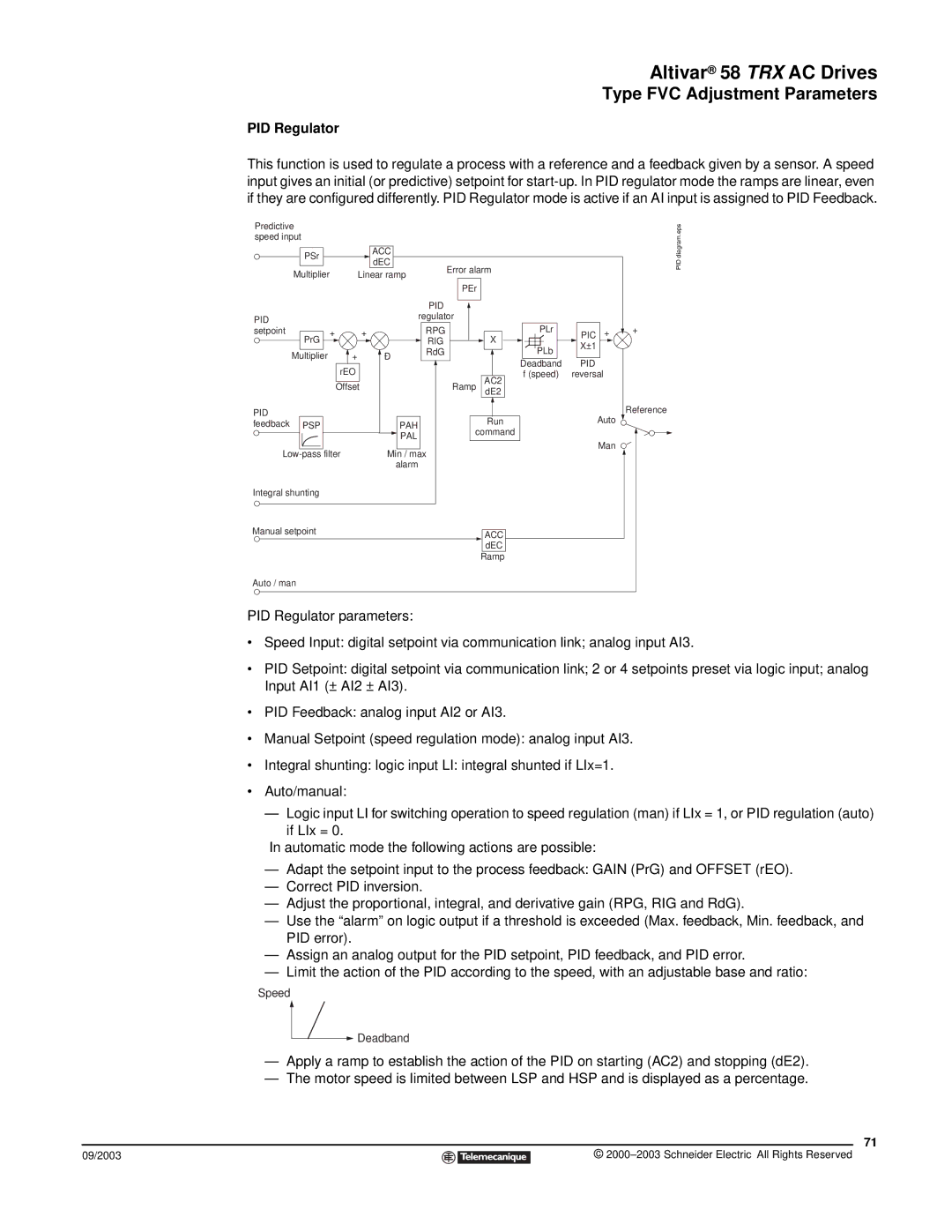
PID Regulator
This function is used to regulate a process with a reference and a feedback given by a sensor. A speed input gives an initial (or predictive) setpoint for
Predictive speed input
| PSr |
|
|
| ACC |
|
| |
|
|
|
| dEC |
| Error alarm | ||
|
|
|
|
|
| |||
Multiplier |
|
|
|
| ||||
Linear ramp | ||||||||
| ||||||||
PEr
PID diagram.eps
|
|
|
|
| PID |
|
PID |
|
|
|
| regulator |
|
|
|
|
|
|
| |
setpoint | + | + |
|
| RPG |
|
| PrG |
|
|
| RIG | X |
| Multiplier | + | Ð |
| RdG |
|
|
|
|
| |||
|
| rEO |
|
|
| AC2 |
|
| Offset |
|
| Ramp | |
|
|
|
| dE2 | ||
PID |
|
|
|
|
| Run |
feedback | PSP |
|
| PAH |
| |
|
|
|
| PAL | command | |
|
|
|
|
|
| |
Min / max |
| |||||
|
|
|
| alarm |
|
|
Integral shunting |
|
|
|
|
| |
PLr | PIC | + |
| ||
PLb | X±1 |
|
|
| |
Deadband | PID |
|
f (speed) | reversal |
|
Auto ![]()
Man
+
Reference
Manual setpoint |
|
|
| |
| ACC |
| ||
|
|
| dEC |
|
|
|
| Ramp |
|
Auto / man |
|
|
| |
PID Regulator parameters:
•Speed Input: digital setpoint via communication link; analog input AI3.
•PID Setpoint: digital setpoint via communication link; 2 or 4 setpoints preset via logic input; analog Input AI1 (± AI2 ± AI3).
•PID Feedback: analog input AI2 or AI3.
•Manual Setpoint (speed regulation mode): analog input AI3.
•Integral shunting: logic input LI: integral shunted if LIx=1.
•Auto/manual:
—Logic input LI for switching operation to speed regulation (man) if LIx = 1, or PID regulation (auto)
if LIx = 0.
In automatic mode the following actions are possible:
—Adapt the setpoint input to the process feedback: GAIN (PrG) and OFFSET (rEO).
—Correct PID inversion.
—Adjust the proportional, integral, and derivative gain (RPG, RIG and RdG).
—Use the “alarm” on logic output if a threshold is exceeded (Max. feedback, Min. feedback, and PID error).
—Assign an analog output for the PID setpoint, PID feedback, and PID error.
—Limit the action of the PID according to the speed, with an adjustable base and ratio:
Speed
![]() Deadband
Deadband
—Apply a ramp to establish the action of the PID on starting (AC2) and stopping (dE2).
—The motor speed is limited between LSP and HSP and is displayed as a percentage.
71
09/2003 |
| © |
| ||
|
|
|