Altivar® 58 TRX AC Drives
Menu Overview
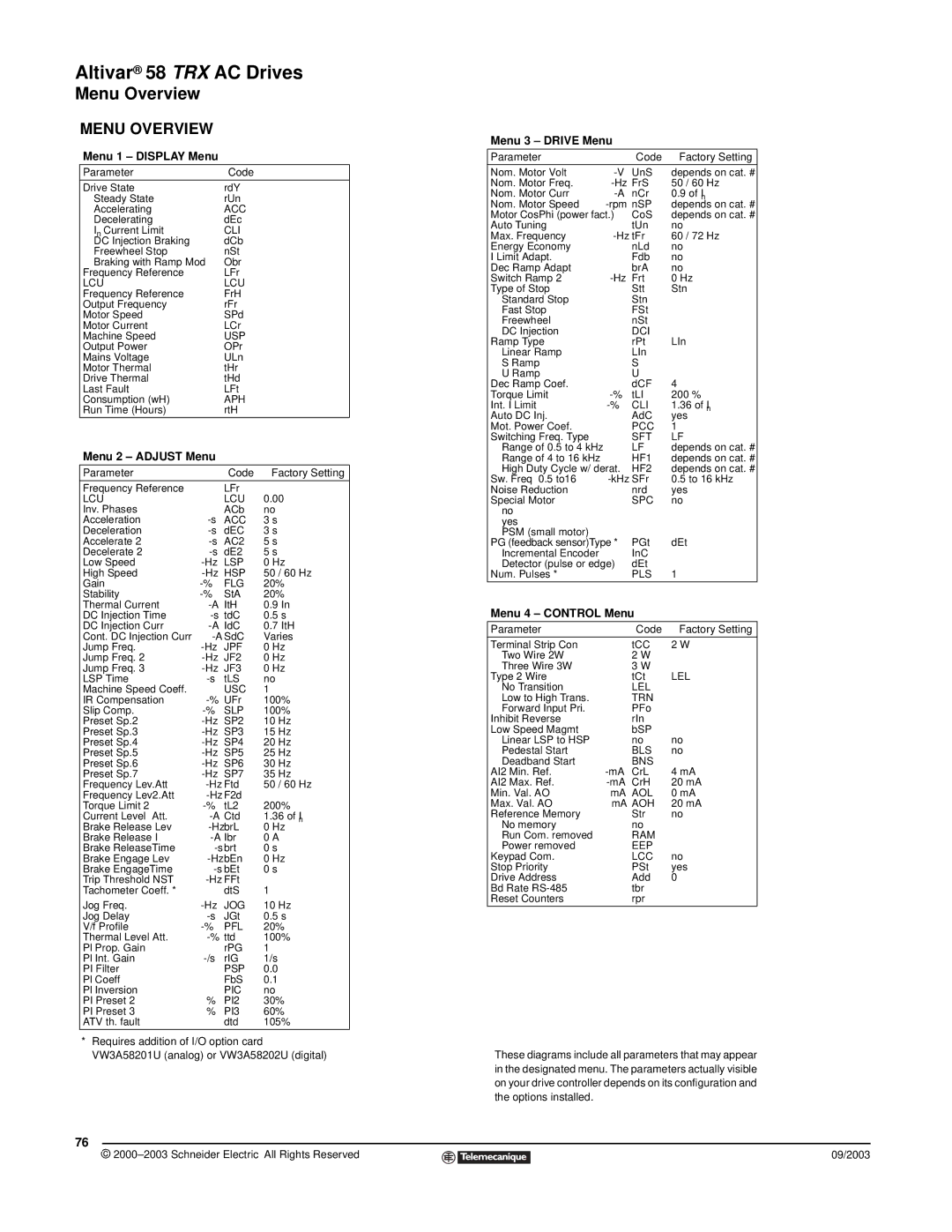
MENU OVERVIEW
Menu 1 – DISPLAY Menu
Parameter | Code |
Drive State | rdY |
Steady State | rUn |
Accelerating | ACC |
Decelerating | dEc |
In Current Limit | CLI |
DC Injection Braking | dCb |
Freewheel Stop | nSt |
Braking with Ramp Mod | Obr |
Frequency Reference | LFr |
LCU | LCU |
Frequency Reference | FrH |
Output Frequency | rFr |
Motor Speed | SPd |
Motor Current | LCr |
Machine Speed | USP |
Output Power | OPr |
Mains Voltage | ULn |
Motor Thermal | tHr |
Drive Thermal | tHd |
Last Fault | LFt |
Consumption (wH) | APH |
Run Time (Hours) | rtH |
Menu 2 – ADJUST Menu
Parameter |
| Code | Factory Setting | |
Frequency Reference |
| LFr |
|
|
LCU |
| LCU | 0.00 | |
Inv. Phases |
| ACb | no |
|
Acceleration | ACC | 3 s |
| |
Deceleration | dEC | 3 s |
| |
Accelerate 2 | AC2 | 5 s |
| |
Decelerate 2 | dE2 | 5 s |
| |
Low Speed | LSP | 0 Hz | ||
High Speed | HSP | 50 | / 60 Hz | |
Gain | FLG | 20% | ||
Stability | StA | 20% | ||
Thermal Current | ItH | 0.9 In | ||
DC Injection Time | tdC | 0.5 s | ||
DC Injection Curr | IdC | 0.7 ItH | ||
Cont. DC Injection Curr | SdC | Varies | ||
Jump Freq. | JPF | 0 Hz | ||
Jump Freq. 2 | JF2 | 0 Hz | ||
Jump Freq. 3 | JF3 | 0 Hz | ||
LSP Time | tLS | no |
| |
Machine Speed Coeff. |
| USC | 1 |
|
IR Compensation | UFr | 100% | ||
Slip Comp. | SLP | 100% | ||
Preset Sp.2 | SP2 | 10 | Hz | |
Preset Sp.3 | SP3 | 15 | Hz | |
Preset Sp.4 | SP4 | 20 | Hz | |
Preset Sp.5 | SP5 | 25 | Hz | |
Preset Sp.6 | SP6 | 30 | Hz | |
Preset Sp.7 | SP7 | 35 | Hz | |
Frequency Lev.Att | Ftd | 50 | / 60 Hz | |
Frequency Lev2.Att | F2d |
|
| |
Torque Limit 2 | tL2 | 200% | ||
Current Level Att. | Ctd | 1.36 of In | ||
Brake Release Lev | brL | 0 Hz | ||
Brake Release I | Ibr | 0 A | ||
Brake ReleaseTime | brt | 0 s |
| |
Brake Engage Lev | bEn | 0 Hz | ||
Brake EngageTime | bEt | 0 s |
| |
Trip Threshold NST | FFt | 1 |
| |
Tachometer Coeff. * |
| dtS |
| |
Jog Freq. | JOG | 10 | Hz | |
Jog Delay | JGt | 0.5 s | ||
V/f Profile | PFL | 20% | ||
Thermal Level Att. | ttd | 100% | ||
Pl Prop. Gain |
| rPG | 1 |
|
Pl Int. Gain | rIG | 1/s |
| |
PI Filter |
| PSP | 0.0 | |
Pl Coeff |
| FbS | 0.1 | |
Pl Inversion |
| PIC | no |
|
PI Preset 2 | % | PI2 | 30% | |
PI Preset 3 | % | PI3 | 60% | |
ATV th. fault |
| dtd | 105% | |
*Requires addition of I/O option card VW3A58201U (analog) or VW3A58202U (digital)
Menu 3 – DRIVE Menu
Parameter |
| Code | Factory Setting |
Nom. Motor Volt | UnS | depends on cat. # | |
Nom. Motor Freq. | FrS | 50 / 60 Hz | |
Nom. Motor Curr | nCr | 0.9 of In | |
Nom. Motor Speed | nSP | depends on cat. # | |
Motor CosPhi (power fact.) | CoS | depends on cat. # | |
Auto Tuning |
| tUn | no |
Max. Frequency | tFr | 60 / 72 Hz | |
Energy Economy |
| nLd | no |
I Limit Adapt. |
| Fdb | no |
Dec Ramp Adapt |
| brA | no |
Switch Ramp 2 | Frt | 0 Hz | |
Type of Stop |
| Stt | Stn |
Standard Stop |
| Stn |
|
Fast Stop |
| FSt |
|
Freewheel |
| nSt |
|
DC Injection |
| DCI | LIn |
Ramp Type |
| rPt | |
Linear Ramp |
| LIn |
|
S Ramp |
| S |
|
U Ramp |
| U | 4 |
Dec Ramp Coef. |
| dCF | |
Torque Limit | tLI | 200 % | |
Int. I Limit | CLI | 1.36 of In | |
Auto DC Inj. |
| AdC | yes |
Mot. Power Coef. |
| PCC | 1 |
Switching Freq. Type |
| SFT | LF |
Range of 0.5 to 4 kHz |
| LF | depends on cat. # |
Range of 4 to 16 kHz |
| HF1 | depends on cat. # |
High Duty Cycle w/ derat. | HF2 | depends on cat. # | |
Sw. Freq 0.5 to16 | SFr | 0.5 to 16 kHz | |
Noise Reduction |
| nrd | yes |
Special Motor |
| SPC | no |
no |
|
|
|
yes |
|
|
|
PSM (small motor) |
|
| dEt |
PG (feedback sensor)Type * | PGt | ||
Incremental Encoder |
| InC |
|
Detector (pulse or edge) | dEt | 1 | |
Num. Pulses * |
| PLS | |
Menu 4 – CONTROL Menu
Parameter |
| Code | Factory Setting |
Terminal Strip Con |
| tCC | 2 W |
Two Wire 2W |
| 2 W |
|
Three Wire 3W |
| 3 W |
|
Type 2 Wire |
| tCt | LEL |
No Transition |
| LEL |
|
Low to High Trans. |
| TRN |
|
Forward Input Pri. |
| PFo |
|
Inhibit Reverse |
| rIn |
|
Low Speed Magmt |
| bSP |
|
Linear LSP to HSP |
| no | no |
Pedestal Start |
| BLS | no |
Deadband Start |
| BNS |
|
AI2 Min. Ref. | CrL | 4 mA | |
AI2 Max. Ref. | CrH | 20 mA | |
Min. Val. AO | mA | AOL | 0 mA |
Max. Val. AO | mA | AOH | 20 mA |
Reference Memory |
| Str | no |
No memory |
| no |
|
Run Com. removed |
| RAM |
|
Power removed |
| EEP |
|
Keypad Com. |
| LCC | no |
Stop Priority |
| PSt | yes |
Drive Address |
| Add | 0 |
Bd Rate |
| tbr |
|
Reset Counters |
| rpr |
|
These diagrams include all parameters that may appear in the designated menu. The parameters actually visible on your drive controller depends on its configuration and the options installed.
76
© |
| 09/2003 |
| ||
|
|
|