Altivar® 58 TRX AC Drives
Power Section Construction Information
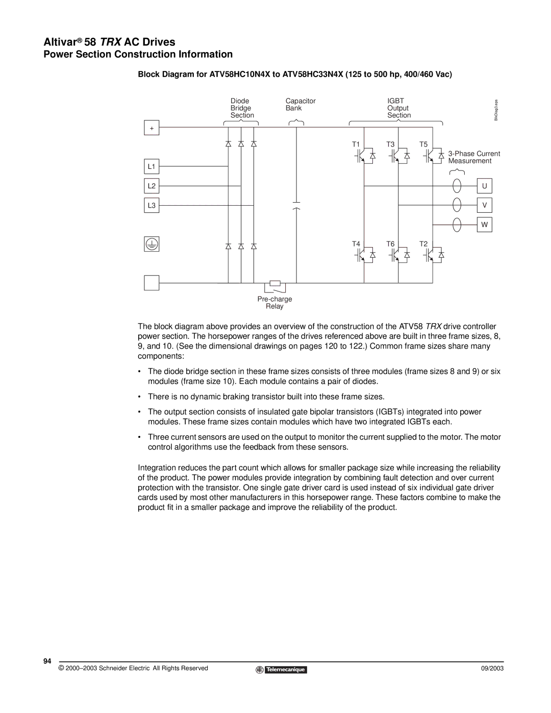
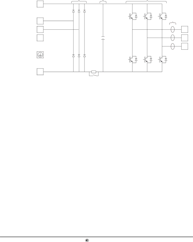
Block Diagram for ATV58HC10N4X to ATV58HC33N4X (125 to 500 hp, 400/460 Vac)
+
L1
L2
L3
−
Diode | Capacitor | IGBT | BlkDiag3.eps |
Bridge | Bank | Output | |
Section |
| Section |
|
| T1 | T3 | T5 |
|
|
| |
|
|
| Measurement |
|
|
| U |
|
|
| V |
|
|
| W |
| T4 | T6 | T2 |
Relay
The block diagram above provides an overview of the construction of the ATV58 TRX drive controller power section. The horsepower ranges of the drives referenced above are built in three frame sizes, 8, 9, and 10. (See the dimensional drawings on pages 120 to 122.) Common frame sizes share many components:
•The diode bridge section in these frame sizes consists of three modules (frame sizes 8 and 9) or six modules (frame size 10). Each module contains a pair of diodes.
•There is no dynamic braking transistor built into these frame sizes.
•The output section consists of insulated gate bipolar transistors (IGBTs) integrated into power modules. These frame sizes contain modules which have two integrated IGBTs each.
•Three current sensors are used on the output to monitor the current supplied to the motor. The motor control algorithms use the feedback from these sensors.
Integration reduces the part count which allows for smaller package size while increasing the reliability of the product. The power modules provide integration by combining fault detection and over current protection with the transistor. One single gate driver card is used instead of six individual gate driver cards used by most other manufacturers in this horsepower range. These factors combine to make the product fit in a smaller package and improve the reliability of the product.
94
© |
| 09/2003 |
| ||
|
|
|