Altivar® 58 TRX AC Drives
Communication Parameters
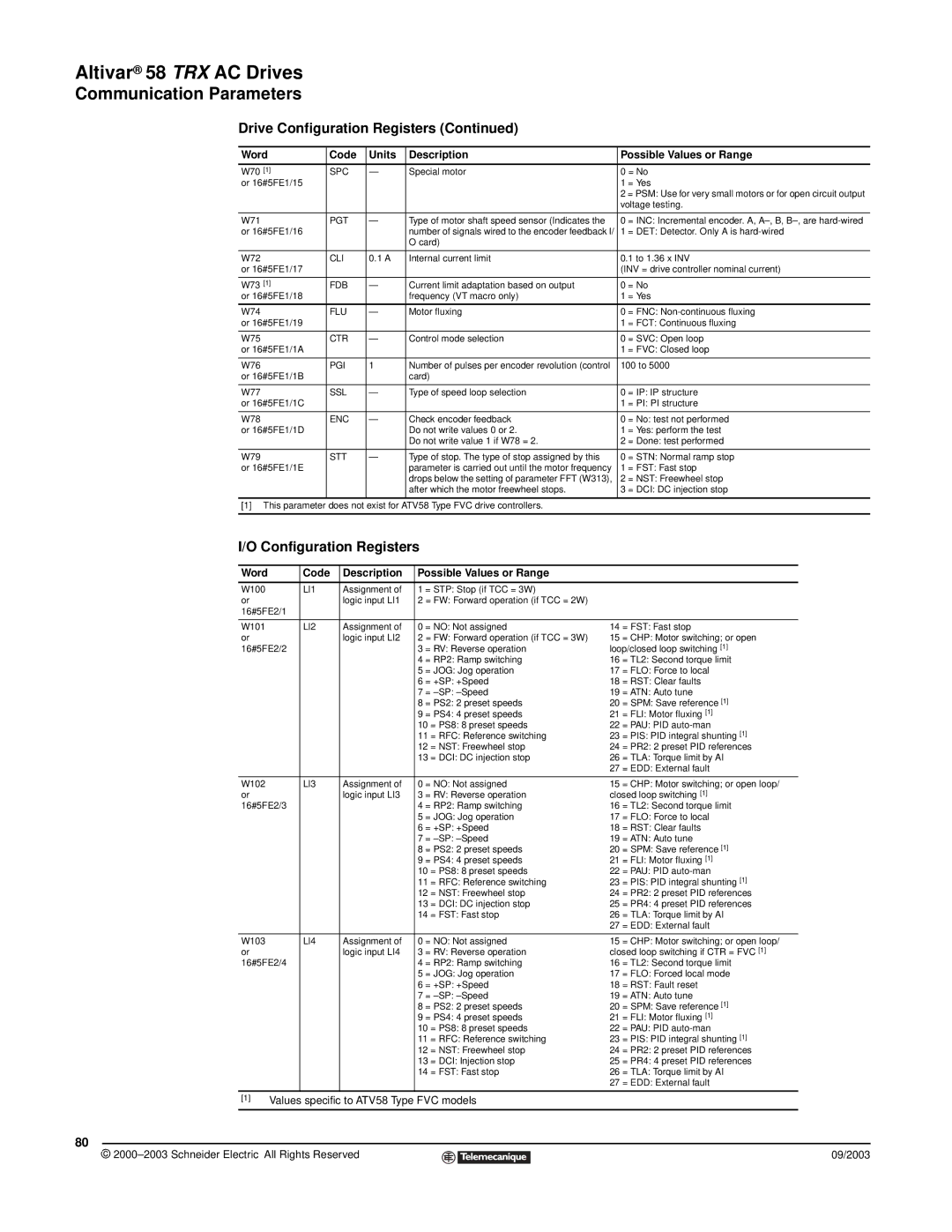
Drive Configuration Registers (Continued)
Word | Code | Units | Description | Possible Values or Range | |
|
|
|
|
| |
W70 [1] | SPC | — | Special motor | 0 = No | |
or 16#5FE1/15 |
|
|
| 1 | = Yes |
|
|
|
| 2 = PSM: Use for very small motors or for open circuit output | |
|
|
|
| voltage testing. | |
|
|
|
|
|
|
W71 | PGT | — | Type of motor shaft speed sensor (Indicates the | 0 | = INC: Incremental encoder. A, |
or 16#5FE1/16 |
|
| number of signals wired to the encoder feedback I/ | 1 | = DET: Detector. Only A is |
|
|
| O card) |
|
|
|
|
|
|
| |
W72 | CLI | 0.1 A | Internal current limit | 0.1 to 1.36 x INV | |
or 16#5FE1/17 |
|
|
| (INV = drive controller nominal current) | |
|
|
|
|
|
|
W73 [1] | FDB | — | Current limit adaptation based on output | 0 | = No |
or 16#5FE1/18 |
|
| frequency (VT macro only) | 1 | = Yes |
|
|
|
|
| |
W74 | FLU | — | Motor fluxing | 0 = FNC: | |
or 16#5FE1/19 |
|
|
| 1 | = FCT: Continuous fluxing |
|
|
|
|
| |
W75 | CTR | — | Control mode selection | 0 = SVC: Open loop | |
or 16#5FE1/1A |
|
|
| 1 | = FVC: Closed loop |
|
|
|
|
| |
W76 | PGI | 1 | Number of pulses per encoder revolution (control | 100 to 5000 | |
or 16#5FE1/1B |
|
| card) |
|
|
|
|
|
|
| |
W77 | SSL | — | Type of speed loop selection | 0 = IP: IP structure | |
or 16#5FE1/1C |
|
|
| 1 | = PI: PI structure |
|
|
|
|
|
|
W78 | ENC | — | Check encoder feedback | 0 | = No: test not performed |
or 16#5FE1/1D |
|
| Do not write values 0 or 2. | 1 | = Yes: perform the test |
|
|
| Do not write value 1 if W78 = 2. | 2 | = Done: test performed |
|
|
|
|
|
|
W79 | STT | — | Type of stop. The type of stop assigned by this | 0 | = STN: Normal ramp stop |
or 16#5FE1/1E |
|
| parameter is carried out until the motor frequency | 1 | = FST: Fast stop |
|
|
| drops below the setting of parameter FFT (W313), | 2 | = NST: Freewheel stop |
|
|
| after which the motor freewheel stops. | 3 | = DCI: DC injection stop |
|
|
|
|
|
|
[1] This parameter does not exist for ATV58 Type FVC drive controllers.
I/O Configuration Registers
Word |
| Code | Description | Possible Values or Range |
|
| ||
|
|
|
|
|
|
| ||
W100 |
| LI1 | Assignment of | 1 = STP: Stop (if TCC = 3W) |
|
| ||
or |
|
| logic input LI1 | 2 = FW: Forward operation (if TCC = 2W) |
|
| ||
16#5FE2/1 |
|
|
|
|
|
|
| |
|
|
|
|
|
|
| ||
W101 |
| LI2 | Assignment of | 0 = NO: Not assigned | 14 | = FST: Fast stop | ||
or |
|
| logic input LI2 | 2 = FW: Forward operation (if TCC = 3W) | 15 | = CHP: Motor switching; or open | ||
16#5FE2/2 |
|
| 3 = RV: Reverse operation | loop/closed loop switching [1] | ||||
|
|
|
| 4 | = RP2: Ramp switching | 16 | = TL2: Second torque limit | |
|
|
|
| 5 | = JOG: Jog operation | 17 | = FLO: Force to local | |
|
|
|
| 6 | = +SP: +Speed | 18 | = RST: Clear faults | |
|
|
|
| 7 | = | 19 | = ATN: Auto tune | |
|
|
|
| 8 | = PS2: 2 preset speeds | 20 | = SPM: Save reference [1] | |
|
|
|
| 9 | = PS4: 4 preset speeds | 21 | = FLI: Motor fluxing [1] | |
|
|
|
| 10 | = PS8: 8 preset speeds | 22 | = PAU: PID | |
|
|
|
| 11 | = RFC: Reference switching | 23 | = PIS: PID integral shunting [1] | |
|
|
|
| 12 | = NST: Freewheel stop | 24 | = PR2: 2 preset PID references | |
|
|
|
| 13 | = DCI: DC injection stop | 26 | = TLA: Torque limit by AI | |
|
|
|
|
|
|
| 27 | = EDD: External fault |
|
|
|
|
|
|
| ||
W102 |
| LI3 | Assignment of | 0 = NO: Not assigned | 15 | = CHP: Motor switching; or open loop/ | ||
or |
|
| logic input LI3 | 3 = RV: Reverse operation | closed loop switching [1] | |||
16#5FE2/3 |
|
| 4 = RP2: Ramp switching | 16 | = TL2: Second torque limit | |||
|
|
|
| 5 | = JOG: Jog operation | 17 | = FLO: Force to local | |
|
|
|
| 6 | = +SP: +Speed | 18 | = RST: Clear faults | |
|
|
|
| 7 | = | 19 | = ATN: Auto tune | |
|
|
|
| 8 | = PS2: 2 preset speeds | 20 | = SPM: Save reference [1] | |
|
|
|
| 9 | = PS4: 4 preset speeds | 21 | = FLI: Motor fluxing [1] | |
|
|
|
| 10 | = PS8: 8 preset speeds | 22 | = PAU: PID | |
|
|
|
| 11 | = RFC: Reference switching | 23 | = PIS: PID integral shunting [1] | |
|
|
|
| 12 | = NST: Freewheel stop | 24 | = PR2: 2 preset PID references | |
|
|
|
| 13 | = DCI: DC injection stop | 25 | = PR4: 4 preset PID references | |
|
|
|
| 14 | = FST: Fast stop | 26 | = TLA: Torque limit by AI | |
|
|
|
|
|
|
| 27 | = EDD: External fault |
|
|
|
|
|
|
| ||
W103 |
| LI4 | Assignment of | 0 = NO: Not assigned | 15 | = CHP: Motor switching; or open loop/ | ||
or |
|
| logic input LI4 | 3 = RV: Reverse operation | closed loop switching if CTR = FVC [1] | |||
16#5FE2/4 |
|
| 4 = RP2: Ramp switching | 16 | = TL2: Second torque limit | |||
|
|
|
| 5 | = JOG: Jog operation | 17 | = FLO: Forced local mode | |
|
|
|
| 6 | = +SP: +Speed | 18 | = RST: Fault reset | |
|
|
|
| 7 | = | 19 | = ATN: Auto tune | |
|
|
|
| 8 | = PS2: 2 preset speeds | 20 | = SPM: Save reference [1] | |
|
|
|
| 9 | = PS4: 4 preset speeds | 21 | = FLI: Motor fluxing [1] | |
|
|
|
| 10 | = PS8: 8 preset speeds | 22 | = PAU: PID | |
|
|
|
| 11 | = RFC: Reference switching | 23 | = PIS: PID integral shunting [1] | |
|
|
|
| 12 | = NST: Freewheel stop | 24 | = PR2: 2 preset PID references | |
|
|
|
| 13 | = DCI: Injection stop | 25 | = PR4: 4 preset PID references | |
|
|
|
| 14 | = FST: Fast stop | 26 | = TLA: Torque limit by AI | |
|
|
|
|
|
|
| 27 | = EDD: External fault |
|
|
|
|
|
|
| ||
[1] | Values specific to ATV58 Type FVC models |
|
| |||||
|
|
|
|
|
|
|
|
|
80
© |
| 09/2003 |
| ||
|
|
|