NOTE: Unlike the previous assignments, which may be assigned to either the analog or digital I/O extension cards, the following assignments can only be assigned to the
Altivar® 58 TRX AC Drives
Assignment of Analog Inputs (AIx)
Encoder Speed Feedback
The Encoder Speed Feedback function can be used to improve the speed regulation based on the encoder feedback signal. It is intended for use in applications in which the load on the motor is changing but accurate speed regulation is critical to the process. The speed feedback input to the drive controller is 24 Vdc. A choice of two different types of encoders can be configured as speed feedback: a NPN sensor type, or a quadrature type encoder.
The NPN sensor type is for use in applications in which the sensor is detecting teeth on a wheel. The 24 Vdc supply on the option card can be used to power the NPN sensor. The quadrature encoders are usually mounted to the motor shaft. An external 24 Vdc power supply for the encoder is recommended. Selection of the encoder is critical for obtaining desired speed regulation.
The NPN sensor type encoders can improve the speed regulation from ± 1% to ± 0.5% of motor rated speed. The quadrature type encoder can improve the speed regulation to ± 0.02% of rated motor speed with a 1024 pulse count encoder.
The maximum signal frequency input with this option card is 33 kHz. Higher pulse count encoders provide greater accuracy. The pulse count must be configured in the drive controller. Use the following to assist in selecting an encoder.
1.Determine the maximum allowable pulse count (pulses per revolution, line count, encoder resolution) with the following formula.
33,000 (max. signal frequency)X60 (seconds/minute) Max. allowable pulse count =
Motor RPM @ drive controller maximum frequency
2.When selecting an incremental encoder: use an encoder with a pulse count closest to, but not greater than, the result of the calculation in step 1. This will result in the highest precision.
3.When selecting a NPN sensor, choose a device that will limit the pulse count to the value determined in step 1. Mechanical play in the toothed wheel or other device will degrade the resulting precision.
4.The maximum pulse frequency of the sensor must not be exceeded. Generally, it is this parameter that limits precision. As an example, the pulse count of a sensor with a maximum frequency of
2000 Hz on a motor with a top speed of 1800 RPM is:
66 | Pulses per revolution = | 2000 (max. signal frequency)X60 (seconds/minute) | |
|
| ||
Example |
|
|
•Motor nominal RPM =1800@ 60 Hz.
•Drive controller maximum frequency = 63 Hz.
•Motor nominal RPM @ 63 Hz = 1800 x (63/60) = 1890
•Maximum pulse count = 33,000 x 60 / 1890 = 1047
•Any pulse count of 1047 or less will work. The higher the pulse count, the higher the feedback resolution. The nearest standard encoder pulse count less than the above calculation is 1024.
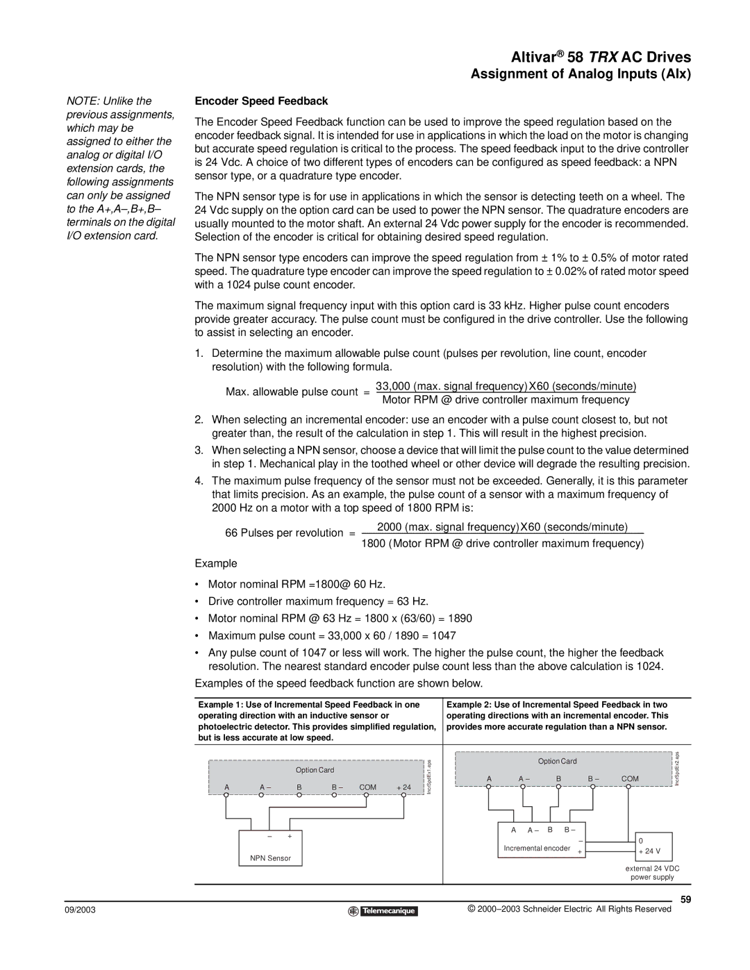
Examples of the speed feedback function are shown below.
Example 1: Use of Incremental Speed Feedback in one |
| Example 2: Use of Incremental Speed Feedback in two |
| |||||||||||||||||||||||||||||||
operating direction with an inductive sensor or |
|
| operating directions with an incremental encoder. This |
| ||||||||||||||||||||||||||||||
photoelectric detector. This provides simplified regulation, | provides more accurate regulation than a NPN sensor. |
| ||||||||||||||||||||||||||||||||
but is less accurate at low speed. |
|
|
|
|
|
|
|
|
|
|
|
|
|
|
|
|
|
|
|
|
|
|
|
|
| |||||||||
|
|
|
|
|
|
|
|
|
|
|
|
|
|
|
|
|
|
|
|
|
|
|
|
|
|
|
|
|
|
|
|
|
|
|
|
|
|
|
|
|
|
|
|
|
|
|
| IncrSpdEx1.eps |
|
|
|
|
|
|
|
|
|
|
|
|
|
|
|
|
|
|
|
| IncrSpdEx2.eps |
|
|
|
|
|
|
|
|
|
|
|
|
|
|
|
|
|
|
|
| Option |
| Card |
|
|
|
|
|
|
|
|
| |||
|
|
|
|
|
|
|
|
|
|
|
|
|
|
|
|
|
|
|
|
|
|
|
|
|
|
|
|
|
|
|
|
|
| |
|
| Option | Card |
|
|
|
|
|
|
|
|
|
|
|
|
|
|
|
|
|
|
|
|
|
|
|
|
| ||||||
|
|
|
|
|
|
|
|
|
|
|
|
|
|
|
|
|
|
|
|
|
|
|
|
|
|
|
|
|
| COM |
| |||
A | A – |
|
|
|
|
|
|
|
|
| COM | + 24 |
|
| A |
| A |
|
|
| B |
|
| B |
|
| ||||||||
|
|
|
|
|
|
|
|
|
|
|
|
|
|
|
|
|
|
|
|
|
|
| ||||||||||||
|
|
|
|
|
|
|
|
|
|
|
|
|
|
|
|
|
|
|
|
|
|
|
|
|
|
|
|
|
|
| ||||
| B | B |
|
|
| A |
|
| A | B |
| B |
|
|
|
|
|
|
|
|
|
| ||||||||||||
|
|
|
|
|
|
|
|
|
|
|
|
|
|
|
|
|
|
|
|
|
| |||||||||||||
| + |
|
|
|
|
|
|
|
|
|
|
|
|
|
|
|
|
|
|
|
|
|
|
|
|
|
|
| ||||||
|
|
|
|
|
|
|
|
|
|
|
|
|
|
| Incremental encoder | + |
|
|
|
|
|
| 0 |
|
| |||||||||
|
|
|
|
|
|
|
|
|
|
|
|
|
|
|
|
|
|
|
|
|
|
| ||||||||||||
|
|
|
|
|
|
|
|
|
|
|
|
|
|
|
|
|
|
|
|
|
|
| ||||||||||||
|
|
|
|
|
|
|
|
|
|
|
|
|
|
|
|
|
|
|
|
|
| + 24 V |
|
| ||||||||||
| NPN Sensor |
|
|
|
|
|
|
|
|
|
|
|
|
|
|
|
|
|
|
|
|
|
|
|
|
|
|
|
|
|
|
| ||
|
|
|
|
|
|
|
|
|
|
|
|
|
|
|
|
|
|
|
|
|
|
|
|
|
|
|
|
|
|
|
|
|
| |
|
|
|
|
|
|
|
|
|
|
|
|
|
|
|
|
|
|
|
|
|
|
|
|
|
|
|
|
|
| external 24 VDC | ||||
|
|
|
|
|
|
|
|
|
|
|
|
|
|
|
|
|
|
|
|
|
|
|
|
|
|
|
|
|
|
| power supply |
| ||
|
|
|
|
|
|
|
|
|
|
|
|
|
|
|
|
|
|
|
|
|
|
|
|
|
|
|
|
|
|
|
|
|
|
|
59
09/2003 |
| © |
| ||
|
|
|