|
|
| Altivar® 58 TRX AC Drives |
|
|
| Communication Parameters |
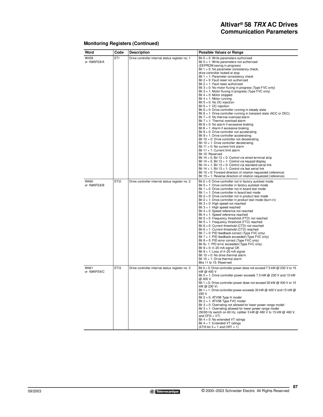
Monitoring Registers (Continued) |
| ||
|
|
|
|
Word | Code | Description | Possible Values or Range |
|
|
|
|
W459 | ETI | Drive controller internal status register no. 1 | Bit 0 = 0: Write parameters authorized |
or 16#5FE8/A |
|
| Bit 0 = 1: Write parameters not authorized |
|
|
| (EEPROM saving in progress) |
|
|
| Bit 1 = 0: No parameter consistency check, |
|
|
| drive controller locked at stop |
|
|
| Bit 1 = 1: Parameter consistency check |
|
|
| Bit 2 = 0: Fault reset not authorized |
|
|
| Bit 2 = 1: Fault reset authorized |
|
|
| Bit 3 = 0: No motor fluxing in progress (Type FVC only) |
|
|
| Bit 3 = 1: Motor fluxing in progress (Type FVC only) |
|
|
| Bit 4 = 0: Motor stopped |
|
|
| Bit 4 = 1: Motor running |
|
|
| Bit 5 = 0: No DC injection |
|
|
| Bit 5 = 1: DC injection |
|
|
| Bit 6 = 0: Drive controller running in steady state |
|
|
| Bit 6 = 1: Drive controller running in transient state (ACC or DEC) |
|
|
| Bit 7 = 0: No thermal overload alarm |
|
|
| Bit 7 = 1: Thermal overload alarm |
|
|
| Bit 8 = 0: No alarm if excessive braking |
|
|
| Bit 8 = 1: Alarm if excessive braking |
|
|
| Bit 9 = 0: Drive controller not accelerating |
|
|
| Bit 9 = 1: Drive controller accelerating |
|
|
| Bit 10 = 0: Drive controller not decelerating |
|
|
| Bit 10 = 1: Drive controller decelerating |
|
|
| Bit 11 = 0: No current limit alarm |
|
|
| Bit 11 = 1: Current limit alarm |
|
|
| Bit 12: Reserved |
|
|
| Bit 14 = 0, Bit 13 = 0: Control via wired terminal strip |
|
|
| Bit 14 = 0, Bit 13 = 1: Control via keypad display |
|
|
| Bit 14 = 1, Bit 13 = 0: Control via standard serial link |
|
|
| Bit 14 = 1, Bit 13 = 1: Control via fast serial link |
|
|
| Bit 15 = 0: Forward direction of rotation requested (reference) |
|
|
| Bit 15 = 1: Reverse direction of rotation requested (reference) |
|
|
|
|
W460 | ETI2 | Drive controller internal status register no. 2 | Bit 0 = 0: Drive controller not in factory autotest mode |
or 16#5FE8/B |
|
| Bit 0 = 1: Drive controller in factory autotest mode |
|
|
| Bit 1 = 0: Drive controller not in board test mode |
|
|
| Bit 1 = 1: Drive controller in board test mode |
|
|
| Bit 2 = 0: Drive controller not in product test mode |
|
|
| Bit 2 = 1: Drive controller in product test mode |
|
|
| Bit 3 = 0: High speed not reached |
|
|
| Bit 3 = 1: High speed reached |
|
|
| Bit 4 = 0: Speed reference not reached |
|
|
| Bit 4 = 1: Speed reference reached |
|
|
| Bit 5 = 0: Frequency threshold (FTD) not reached |
|
|
| Bit 5 = 1: Frequency threshold (FTD) reached |
|
|
| Bit 6 = 0: Current threshold (CTD) not reached |
|
|
| Bit 6 = 1: Current threshold (CTD) reached |
|
|
| Bit 7 = 0: PID feedback correct (Type FVC only) |
|
|
| Bit 7 = 1: PID feedback exceeded (Type FVC only) |
|
|
| Bit 8 = 0: PID error correct (Type FVC only) |
|
|
| Bit 8= 1: PID error exceeded (Type FVC only) |
|
|
| Bit 9 = 0: |
|
|
| Bit 9 = 1: Loss of |
|
|
| Bit 10 = 0: No drive thermal alarm |
|
|
| Bit 10 = 1: Drive thermal alarm |
|
|
| Bits 11 to 15: Reserved |
|
|
|
|
W461 | ETI3 | Drive controller internal status register no. 3 | Bit 0 = 0: Drive controller power does not exceed 7.5 kW @ 230 V or 15 |
or 16#5FE8/C |
|
| kW @ 400 V |
|
|
| Bit 0 = 1: Drive controller power exceeds 7.5 kW @ 230 V and 15 kW |
|
|
| @ 400 V |
|
|
| Bit 1 = 0: Drive controller power does not exceed 30 kW @ 400 V or 15 |
|
|
| kW @ 230 V) |
|
|
| Bit 1 = 1: Drive controller power exceeds 30 kW @ 400 V and 15 kW @ |
|
|
| 230 V |
|
|
| Bit 2 = 0: ATV58 Type H model |
|
|
| Bit 2 = 1: ATV58 Type FVC model |
|
|
| Bit 3 = 0: Overrating not allowed for lower power range model |
|
|
| Bit 3 = 1: Overrating allowed for lower power range model |
|
|
| (50/60 Hz switch on 60 Hz, caliber 3 kW @ 460 V to 15 kW @ 460 V, |
|
|
| and CFG = VT) |
|
|
| Bit 4 = 0: No extended VT ratings |
|
|
| Bit 4 = 1: Extended VT ratings |
|
|
| (ETI3 bit 3 = 1 and ORT = 1) |
|
|
|
|
87
09/2003 |
| © |
| ||
|
|
|