Altivar® 58 TRX AC Drives
Communication Parameters
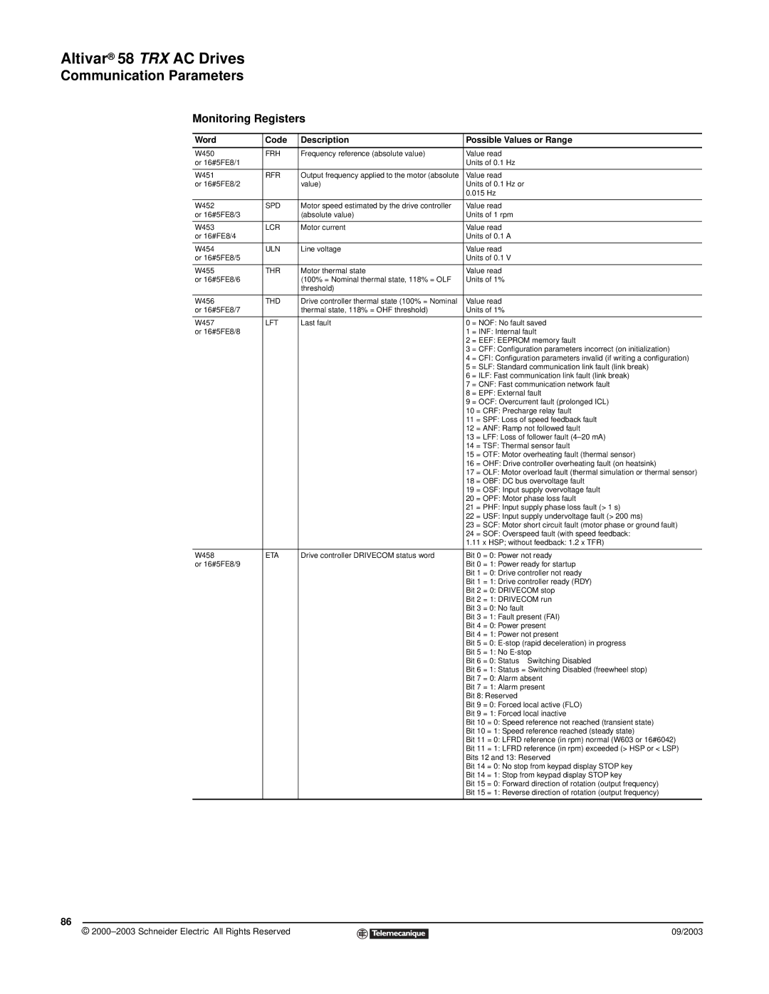
Monitoring Registers
Word | Code | Description | Possible Values or Range | |
|
|
|
| |
W450 | FRH | Frequency reference (absolute value) | Value read | |
or 16#5FE8/1 |
|
| Units of 0.1 Hz | |
|
|
|
| |
W451 | RFR | Output frequency applied to the motor (absolute | Value read | |
or 16#5FE8/2 |
| value) | Units of 0.1 Hz or | |
|
|
| 0.015 Hz | |
|
|
|
| |
W452 | SPD | Motor speed estimated by the drive controller | Value read | |
or 16#5FE8/3 |
| (absolute value) | Units of 1 rpm | |
|
|
|
| |
W453 | LCR | Motor current | Value read | |
or 16#FE8/4 |
|
| Units of 0.1 A | |
|
|
|
| |
W454 | ULN | Line voltage | Value read | |
or 16#5FE8/5 |
|
| Units of 0.1 V | |
|
|
|
| |
W455 | THR | Motor thermal state | Value read | |
or 16#5FE8/6 |
| (100% = Nominal thermal state, 118% = OLF | Units of 1% | |
|
| threshold) |
|
|
|
|
|
| |
W456 | THD | Drive controller thermal state (100% = Nominal | Value read | |
or 16#5FE8/7 |
| thermal state, 118% = OHF threshold) | Units of 1% | |
|
|
|
| |
W457 | LFT | Last fault | 0 = NOF: No fault saved | |
or 16#5FE8/8 |
|
| 1 = INF: Internal fault | |
|
|
| 2 = EEF: EEPROM memory fault | |
|
|
| 3 = CFF: Configuration parameters incorrect (on initialization) | |
|
|
| 4 = CFI: Configuration parameters invalid (if writing a configuration) | |
|
|
| 5 = SLF: Standard communication link fault (link break) | |
|
|
| 6 = ILF: Fast communication link fault (link break) | |
|
|
| 7 = CNF: Fast communication network fault | |
|
|
| 8 = EPF: External fault | |
|
|
| 9 = OCF: Overcurrent fault (prolonged ICL) | |
|
|
| 10 | = CRF: Precharge relay fault |
|
|
| 11 | = SPF: Loss of speed feedback fault |
|
|
| 12 | = ANF: Ramp not followed fault |
|
|
| 13 | = LFF: Loss of follower fault |
|
|
| 14 | = TSF: Thermal sensor fault |
|
|
| 15 | = OTF: Motor overheating fault (thermal sensor) |
|
|
| 16 | = OHF: Drive controller overheating fault (on heatsink) |
|
|
| 17 | = OLF: Motor overload fault (thermal simulation or thermal sensor) |
|
|
| 18 | = OBF: DC bus overvoltage fault |
|
|
| 19 | = OSF: Input supply overvoltage fault |
|
|
| 20 | = OPF: Motor phase loss fault |
|
|
| 21 | = PHF: Input supply phase loss fault (> 1 s) |
|
|
| 22 | = USF: Input supply undervoltage fault (> 200 ms) |
|
|
| 23 | = SCF: Motor short circuit fault (motor phase or ground fault) |
|
|
| 24 | = SOF: Overspeed fault (with speed feedback: |
|
|
| 1.11 x HSP; without feedback: 1.2 x TFR) | |
|
|
|
| |
W458 | ETA | Drive controller DRIVECOM status word | Bit 0 = 0: Power not ready | |
or 16#5FE8/9 |
|
| Bit 0 = 1: Power ready for startup | |
|
|
| Bit 1 = 0: Drive controller not ready | |
|
|
| Bit 1 = 1: Drive controller ready (RDY) | |
|
|
| Bit 2 = 0: DRIVECOM stop | |
|
|
| Bit 2 = 1: DRIVECOM run | |
|
|
| Bit 3 = 0: No fault | |
|
|
| Bit 3 = 1: Fault present (FAI) | |
|
|
| Bit 4 = 0: Power present | |
|
|
| Bit 4 = 1: Power not present | |
|
|
| Bit 5 = 0: | |
|
|
| Bit 5 = 1: No | |
|
|
| Bit 6 = 0: Status ≠ Switching Disabled | |
|
|
| Bit 6 = 1: Status = Switching Disabled (freewheel stop) | |
|
|
| Bit 7 = 0: Alarm absent | |
|
|
| Bit 7 = 1: Alarm present | |
|
|
| Bit 8: Reserved | |
|
|
| Bit 9 = 0: Forced local active (FLO) | |
|
|
| Bit 9 = 1: Forced local inactive | |
|
|
| Bit 10 = 0: Speed reference not reached (transient state) | |
|
|
| Bit 10 = 1: Speed reference reached (steady state) | |
|
|
| Bit 11 = 0: LFRD reference (in rpm) normal (W603 or 16#6042) | |
|
|
| Bit 11 = 1: LFRD reference (in rpm) exceeded (> HSP or < LSP) | |
|
|
| Bits 12 and 13: Reserved | |
|
|
| Bit 14 = 0: No stop from keypad display STOP key | |
|
|
| Bit 14 = 1: Stop from keypad display STOP key | |
|
|
| Bit 15 = 0: Forward direction of rotation (output frequency) | |
|
|
| Bit 15 = 1: Reverse direction of rotation (output frequency) | |
|
|
|
|
|
86
© |
| 09/2003 |
| ||
|
|
|