|
|
|
| Altivar® 58 TRX AC Drives |
|
|
|
| Communication Parameters |
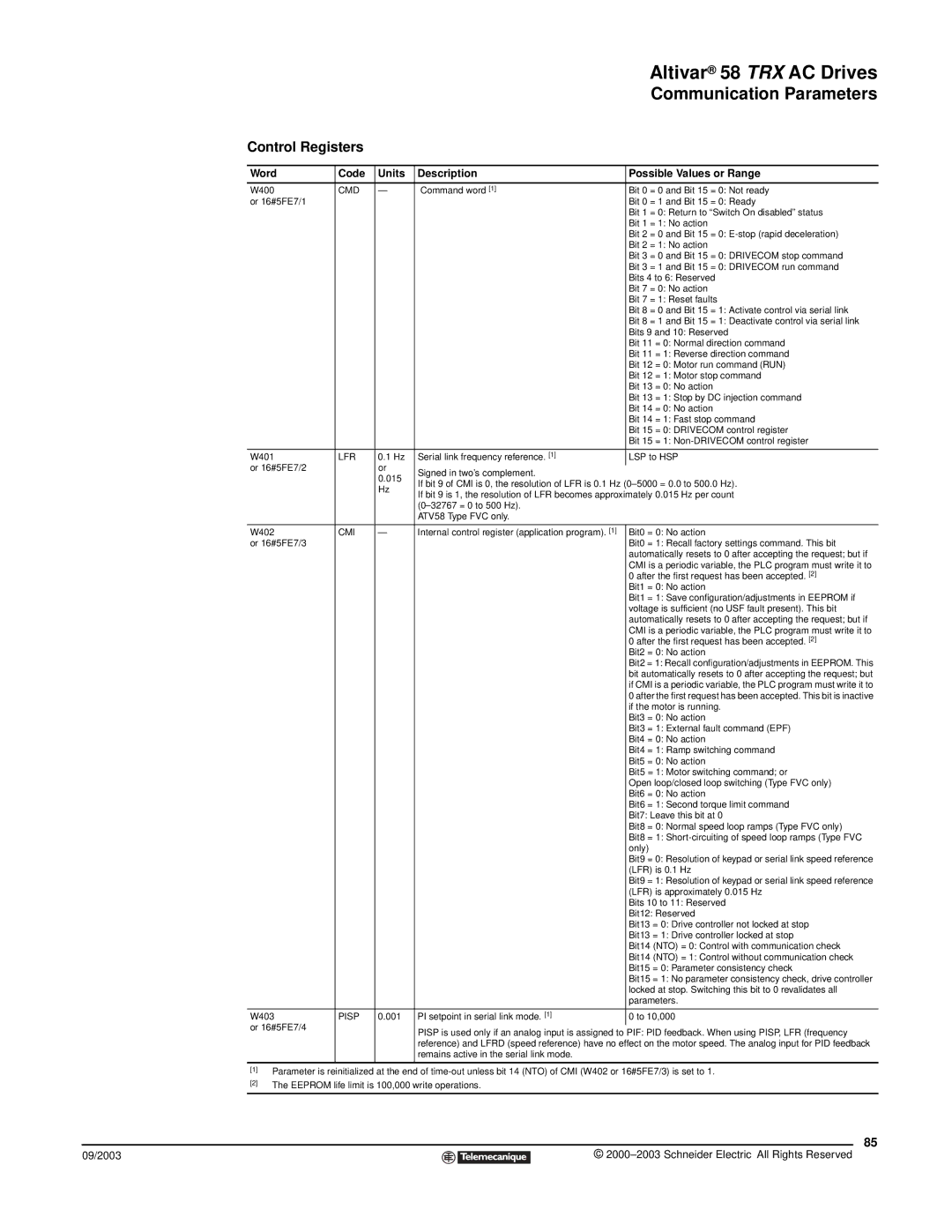
Control Registers |
|
|
| |
|
|
|
|
|
Word | Code | Units | Description | Possible Values or Range |
|
|
|
|
|
W400 | CMD | — | Command word [1] | Bit 0 = 0 and Bit 15 = 0: Not ready |
or 16#5FE7/1 |
|
|
| Bit 0 = 1 and Bit 15 = 0: Ready |
|
|
|
| Bit 1 = 0: Return to “Switch On disabled” status |
|
|
|
| Bit 1 = 1: No action |
|
|
|
| Bit 2 = 0 and Bit 15 = 0: |
|
|
|
| Bit 2 = 1: No action |
|
|
|
| Bit 3 = 0 and Bit 15 = 0: DRIVECOM stop command |
|
|
|
| Bit 3 = 1 and Bit 15 = 0: DRIVECOM run command |
|
|
|
| Bits 4 to 6: Reserved |
|
|
|
| Bit 7 = 0: No action |
|
|
|
| Bit 7 = 1: Reset faults |
|
|
|
| Bit 8 = 0 and Bit 15 = 1: Activate control via serial link |
|
|
|
| Bit 8 = 1 and Bit 15 = 1: Deactivate control via serial link |
|
|
|
| Bits 9 and 10: Reserved |
|
|
|
| Bit 11 = 0: Normal direction command |
|
|
|
| Bit 11 = 1: Reverse direction command |
|
|
|
| Bit 12 = 0: Motor run command (RUN) |
|
|
|
| Bit 12 = 1: Motor stop command |
|
|
|
| Bit 13 = 0: No action |
|
|
|
| Bit 13 = 1: Stop by DC injection command |
|
|
|
| Bit 14 = 0: No action |
|
|
|
| Bit 14 = 1: Fast stop command |
|
|
|
| Bit 15 = 0: DRIVECOM control register |
|
|
|
| Bit 15 = 1: |
|
|
|
|
|
W401 | LFR | 0.1 Hz | Serial link frequency reference. [1] | LSP to HSP |
or 16#5FE7/2 |
| or | Signed in two’s complement. |
|
|
| 0.015 |
| |
|
| If bit 9 of CMI is 0, the resolution of LFR is 0.1 Hz | ||
|
| Hz | ||
|
| If bit 9 is 1, the resolution of LFR becomes approximately 0.015 Hz per count | ||
|
|
| ||
|
|
|
| |
|
|
| ATV58 Type FVC only. |
|
|
|
|
|
|
W402 | CMI | — | Internal control register (application program). [1] | Bit0 = 0: No action |
or 16#5FE7/3 |
|
|
| Bit0 = 1: Recall factory settings command. This bit |
|
|
|
| automatically resets to 0 after accepting the request; but if |
|
|
|
| CMI is a periodic variable, the PLC program must write it to |
|
|
|
| 0 after the first request has been accepted. [2] |
|
|
|
| Bit1 = 0: No action |
|
|
|
| Bit1 = 1: Save configuration/adjustments in EEPROM if |
|
|
|
| voltage is sufficient (no USF fault present). This bit |
|
|
|
| automatically resets to 0 after accepting the request; but if |
|
|
|
| CMI is a periodic variable, the PLC program must write it to |
|
|
|
| 0 after the first request has been accepted. [2] |
|
|
|
| Bit2 = 0: No action |
|
|
|
| Bit2 = 1: Recall configuration/adjustments in EEPROM. This |
|
|
|
| bit automatically resets to 0 after accepting the request; but |
|
|
|
| if CMI is a periodic variable, the PLC program must write it to |
|
|
|
| 0 after the first request has been accepted. This bit is inactive |
|
|
|
| if the motor is running. |
|
|
|
| Bit3 = 0: No action |
|
|
|
| Bit3 = 1: External fault command (EPF) |
|
|
|
| Bit4 = 0: No action |
|
|
|
| Bit4 = 1: Ramp switching command |
|
|
|
| Bit5 = 0: No action |
|
|
|
| Bit5 = 1: Motor switching command; or |
|
|
|
| Open loop/closed loop switching (Type FVC only) |
|
|
|
| Bit6 = 0: No action |
|
|
|
| Bit6 = 1: Second torque limit command |
|
|
|
| Bit7: Leave this bit at 0 |
|
|
|
| Bit8 = 0: Normal speed loop ramps (Type FVC only) |
|
|
|
| Bit8 = 1: |
|
|
|
| only) |
|
|
|
| Bit9 = 0: Resolution of keypad or serial link speed reference |
|
|
|
| (LFR) is 0.1 Hz |
|
|
|
| Bit9 = 1: Resolution of keypad or serial link speed reference |
|
|
|
| (LFR) is approximately 0.015 Hz |
|
|
|
| Bits 10 to 11: Reserved |
|
|
|
| Bit12: Reserved |
|
|
|
| Bit13 = 0: Drive controller not locked at stop |
|
|
|
| Bit13 = 1: Drive controller locked at stop |
|
|
|
| Bit14 (NTO) = 0: Control with communication check |
|
|
|
| Bit14 (NTO) = 1: Control without communication check |
|
|
|
| Bit15 = 0: Parameter consistency check |
|
|
|
| Bit15 = 1: No parameter consistency check, drive controller |
|
|
|
| locked at stop. Switching this bit to 0 revalidates all |
|
|
|
| parameters. |
|
|
|
|
|
W403 | PISP | 0.001 | PI setpoint in serial link mode. [1] | 0 to 10,000 |
or 16#5FE7/4 |
|
| PISP is used only if an analog input is assigned to PIF: PID feedback. When using PISP, LFR (frequency | |
|
|
| ||
|
|
| reference) and LFRD (speed reference) have no effect on the motor speed. The analog input for PID feedback | |
|
|
| remains active in the serial link mode. |
|
|
|
|
|
|
[1]Parameter is reinitialized at the end of
[2]The EEPROM life limit is 100,000 write operations.
85
09/2003 |
| © |
| ||
|
|
|