Altivar® 58 TRX AC Drives
Assignment of Logic Inputs (LIx)
| f (Hz) | RefSwitch.eps |
|
| |
AI1 |
| |
AI2 |
| |
|
| t |
Forward | 1 |
|
or | 0 | t |
Reverse | ||
| 1 |
|
LIx 0 | t | |
Connection Diagram for Reference Switching |
| |||
LIx | COM | AI1 | +10 | AI2 |
| – | + |
| |
|
|
|
| |
|
|
|
| |
+ 24 V |
| Remote |
|
|
|
|
|
| |
|
| Signal |
|
|
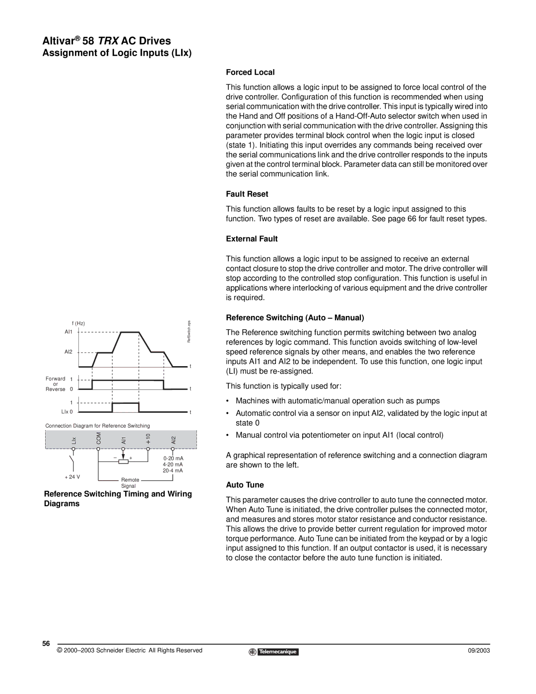
Reference Switching Timing and Wiring Diagrams
56
©
Forced Local
This function allows a logic input to be assigned to force local control of the drive controller. Configuration of this function is recommended when using serial communication with the drive controller. This input is typically wired into the Hand and Off positions of a
Fault Reset
This function allows faults to be reset by a logic input assigned to this function. Two types of reset are available. See page 66 for fault reset types.
External Fault
This function allows a logic input to be assigned to receive an external contact closure to stop the drive controller and motor. The drive controller will stop according to the controlled stop configuration. This function is useful in applications where interlocking of various equipment and the drive controller is required.
Reference Switching (Auto – Manual)
The Reference switching function permits switching between two analog references by logic command. This function avoids switching of
This function is typically used for:
•Machines with automatic/manual operation such as pumps
•Automatic control via a sensor on input AI2, validated by the logic input at state 0
•Manual control via potentiometer on input AI1 (local control)
A graphical representation of reference switching and a connection diagram are shown to the left.
Auto Tune
This parameter causes the drive controller to auto tune the connected motor. When Auto Tune is initiated, the drive controller pulses the connected motor, and measures and stores motor stator resistance and conductor resistance. This allows the drive to provide better current regulation for improved motor torque performance. Auto Tune can be initiated from the keypad or by a logic input assigned to this function. If an output contactor is used, it is necessary to close the contactor before the auto tune function is initiated.
09/2003