Altivar® 58 TRX AC Drives
Wiring Recommendations
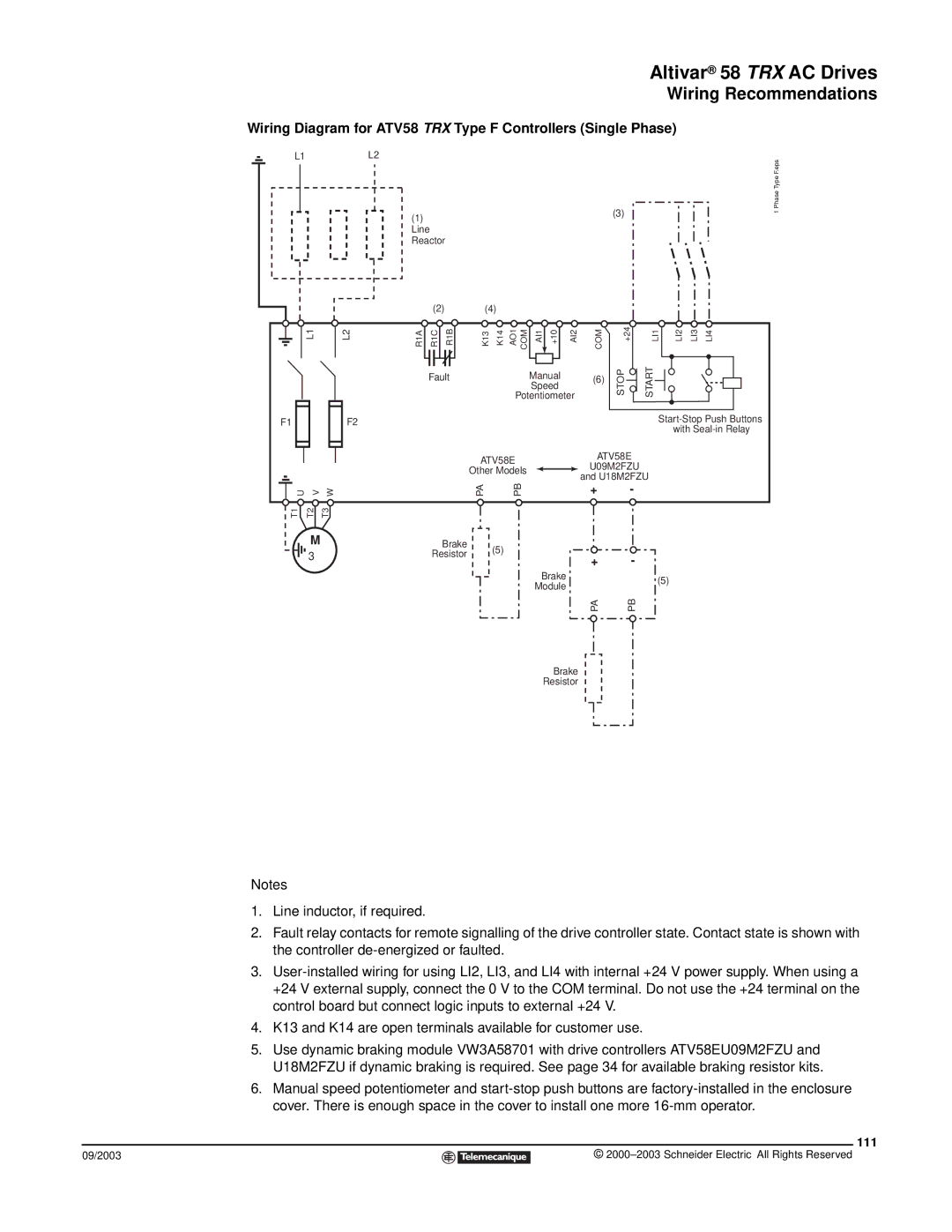
Wiring Diagram for ATV58 TRX Type F Controllers (Single Phase)
L1L2
(1) | (3) |
| |
Line |
|
Reactor |
|
|
|
|
| (2) | (4) |
|
|
|
|
|
|
|
|
|
|
| |
| L1 | L2 | R1A | R1C | R1B | K13 K14 | AO1 COM | AI1 | +10 | AI2 | COM | STOP | +24 | LI1 | LI2 | LI3 | LI4 |
|
|
|
| Fault |
|
| Manual |
| (6) |
| START |
|
|
| |||
|
|
|
|
|
|
|
| Speed |
|
|
|
|
|
|
|
| |
|
|
|
|
|
|
| Potentiometer |
|
|
|
|
|
|
| |||
F1 |
| F2 |
|
|
|
|
|
|
|
|
|
|
|
| |||
|
|
|
|
|
|
|
|
|
|
|
|
| with | ||||
|
|
|
|
|
|
|
|
|
|
|
|
|
|
| |||
|
|
|
|
|
| ATV58E |
|
|
| ATV58E |
|
|
|
| |||
|
|
|
|
|
|
|
|
| U09M2FZU |
|
|
|
| ||||
|
|
|
|
|
| Other Models |
|
|
|
|
|
|
| ||||
|
|
|
|
|
|
|
|
| and U18M2FZU |
|
|
| |||||
|
|
|
|
|
|
|
|
|
|
|
|
|
| ||||
U | V | W |
|
|
| PA | PB |
|
|
| + |
| - |
|
|
|
|
T1 | T2 | T3 |
|
|
|
|
|
|
|
|
|
|
|
|
|
|
|
| M |
|
|
| Brake | (5) |
|
|
|
|
|
|
|
|
|
|
|
| 3φ |
|
| Resistor |
|
|
|
| + |
| - |
|
|
|
| ||
|
|
|
|
|
|
|
|
|
|
|
|
| |||||
|
|
|
|
|
|
|
|
|
|
|
|
|
|
|
| ||
|
|
|
|
|
|
|
| Brake |
|
|
|
| (5) |
|
| ||
|
|
|
|
|
|
|
| Module |
|
|
|
|
|
| |||
|
|
|
|
|
|
|
|
|
|
|
|
|
|
|
| ||
|
|
|
|
|
|
|
|
|
|
| PA |
| PB |
|
|
|
|
1 Phase Type F.eps
Brake
Resistor
Notes
1.Line inductor, if required.
2.Fault relay contacts for remote signalling of the drive controller state. Contact state is shown with the controller
3.
4.K13 and K14 are open terminals available for customer use.
5.Use dynamic braking module VW3A58701 with drive controllers ATV58EU09M2FZU and U18M2FZU if dynamic braking is required. See page 34 for available braking resistor kits.
6.Manual speed potentiometer and
111
09/2003 |
| © |
| ||
|
|
|