11.. . APPENDIX A: MASTER ICON REFERENCE
MA-LO; +/- 20 MADC FULL SCALE CURRENT INPUT ICON
FUNCTION:
Performs the analog channel selection, amplification, and
INPUTS:
Hardware: No signal input shown on Net for Program Net connections.
Update Clock: Output is updated with new reading upon each Update Clock pulse when Enable input is unconnected or Hi.
Enable: Processing of icon is allowed when Enable pin is unconnected or connected and Enable signal is TRUE.
OUTPUTS:
Output Signal: Data type signal. The Units of the output are mA.
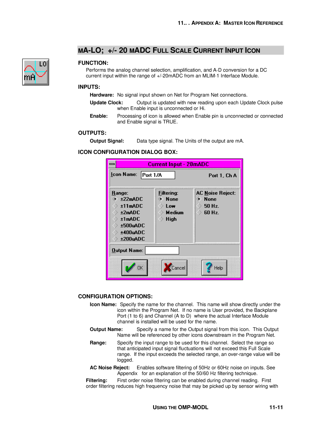
ICON CONFIGURATION DIALOG BOX:
CONFIGURATION OPTIONS:
Icon Name: Specify the name for the channel. This name will show directly under the icon within the Program Net. If no name is User provided, the Backplane Port (1 to 6) and Channel (A to D) where the actual Interface Module channel is installed will be used for the name.
Output Name: Specify a name for the Output signal from this icon. This Output Name will be referenced by other icons downstream in the Program Net.
Range: Specify the input range to be used for this channel. Select the range so that anticipated input signal fluctuations will not exceed this Full Scale range. If the input exceeds the selected range, an
AC Noise Reject: Enables software filtering of 50Hz or 60Hz noise on inputs. See Appendix for an explanation of the 50/60 Hz filtering technique.
Filtering: First order noise filtering can be enabled during channel reading. First order filtering reduces high frequency noise that may be picked up by sensor wiring with
USING THE |
|