Omega Vehicle Security OMP-MODL manual Thermocouple Connection, MLIM-1 Thermocouple Application

Models: OMP-MODL

1 297
Download 297 pages 51.3 Kb
Page 48
Image 48

Thermo-

couple Icon

3... INTERFACE MODULES

Commonly, this fuse is blown during installation of 4- 20mA current channels where the power supply powering the 4-20mA transmitter is accidently shorted directly across the logger input channel. To avoid this inconvenience, always check wiring prior to powering up system power supplies.

MLIM-1; THERMOCOUPLE APPLICATION

Thermocouple Connection:

To utilize an MLIM-1 channel as a thermocouple input, configure that channel’s Interface Module Configuration Switch per Table 3... -4. Channels configured as thermocouple inputs utilize three terminal strip connections per input; Positive lead, Negative lead, and Shield.

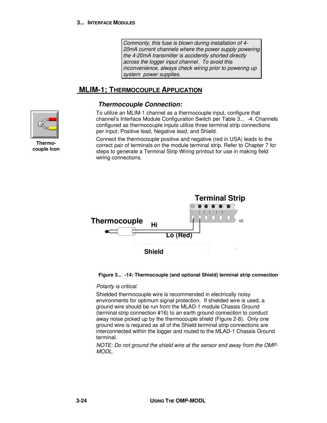
Connect the thermocouple positive and negative (red in USA) leads to the correct pair of terminals on the module terminal strip. Refer to Chapter 7 for steps to generate a Terminal Strip Wiring printout for use in making field wiring connections.

Terminal Strip

1 2 3 4 5 6

Thermocouple

ML055


Hi


Lo (Red)


Shield

Figure 3... -14: Thermocouple (and optional Shield) terminal strip connection

Polarity is critical.

Shielded thermocouple wire is recommended in electrically noisy environments for optimum signal protection. If shielded wire is used, a ground wire should be run from the MLAD-1 module Chassis Ground (terminal strip connection #16) to an earth ground connection to conduct away noise picked up by the thermocouple shield (Figure 2-8). Only one ground wire is required as all of the Shield terminal strip connections are interconnected within the logger and routed to the MLAD-1 Chassis Ground terminal.

NOTE: Do not ground the shield wire at the sensor end away from the OMP- MODL.

3-24

USING THE OMP-MODL

Page 48
Image 48
Omega Vehicle Security OMP-MODL manual Thermocouple Connection, MLIM-1 Thermocouple Application