3... INTERFACE MODULES
Input / Range | SW 1 | SW2 | SW3 | SW4 |
Thermocouples | OFF | OFF | OFF | ON |
VDC up through |
|
|
|
|
VDC up through | OFF | OFF | ON | OFF |
VDC up through | OFF | ON | OFF | OFF |
All Current (mADC) Ranges | ON | OFF | OFF | ON |
Table 3...
MLIM-1 Channel Configuration via Software:
When a
|
|
|
| Ground Ref |
ON |
|
|
| jumpers |
|
|
|
| |
|
|
|
| Fuse (one per |
|
|
|
| channel) |
OFF | Chan A | Chan B | Chan C | Chan D |
Configuration Switches (one per channel)
I/O Wiring Terminal
Strip
ml013
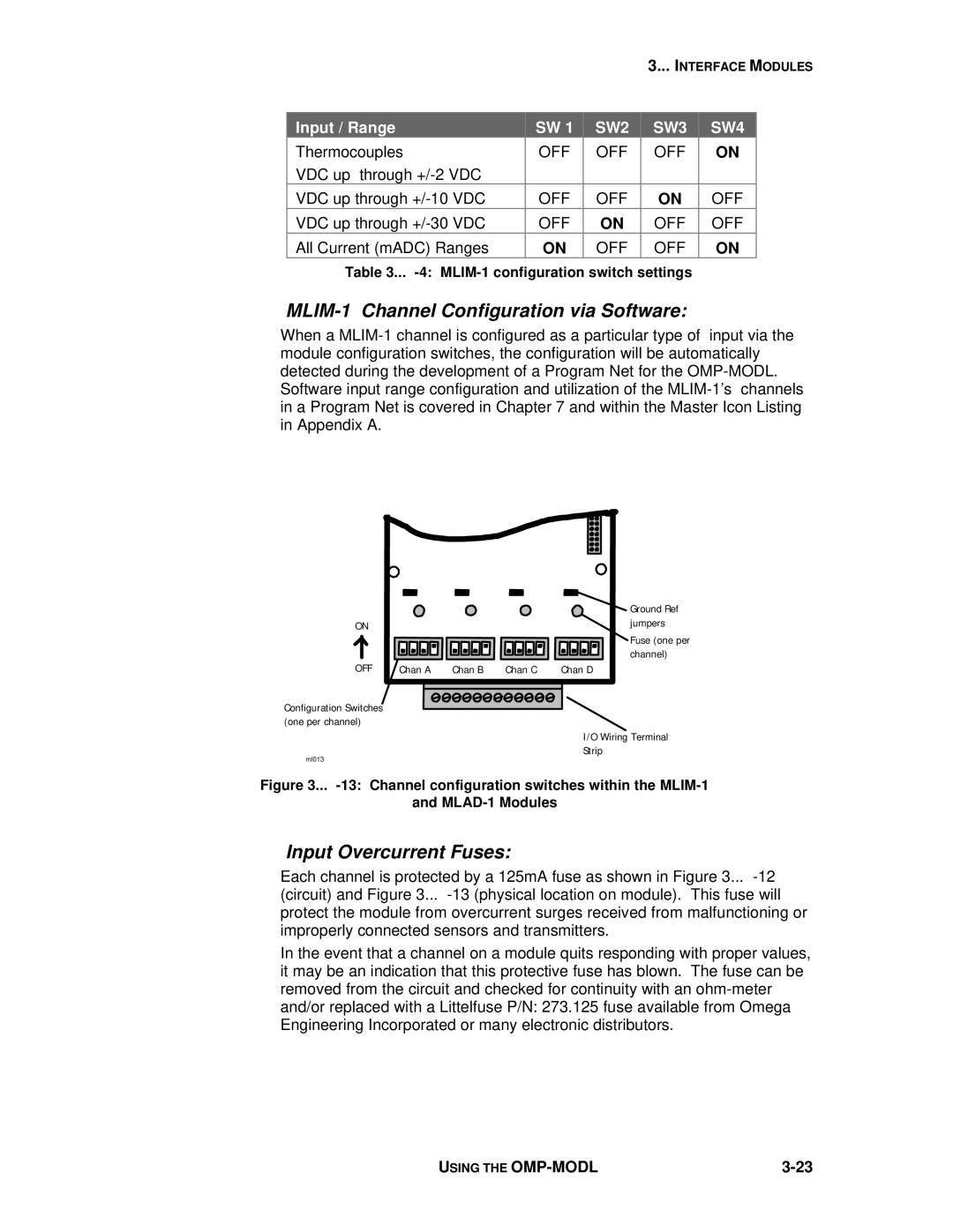
Figure 3... -13: Channel configuration switches within the MLIM-1
and MLAD-1 Modules
Input Overcurrent Fuses:
Each channel is protected by a 125mA fuse as shown in Figure 3...
In the event that a channel on a module quits responding with proper values, it may be an indication that this protective fuse has blown. The fuse can be removed from the circuit and checked for continuity with an
USING THE |
