7... HYPERNET™ I CON BASED PROGRAMMING
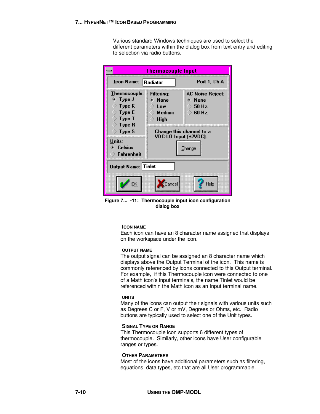
Various standard Windows techniques are used to select the different parameters within the dialog box from text entry and editing to selection via radio buttons.
Figure 7... -11: Thermocouple input icon configuration
dialog box
ICON NAME
Each icon can have an 8 character name assigned that displays on the workspace under the icon.
OUTPUT NAME
The output signal can be assigned an 8 character name which displays above the Output Terminal of the icon. This name is commonly referenced by icons connected to this Output terminal. For example, if this Thermocouple icon were connected to one of a Math icon’s input terminals, the name Tinlet would be referenced within the Math icon as an Input terminal name.
UNITS
Many of the icons can output their signals with various units such as Degrees C or F, V or mV, Degrees or Ohms, etc. Radio buttons are typically used to select one of the Unit types.
SIGNAL TYPE OR RANGE
This Thermocouple icon supports 6 different types of thermocouple. Similarly, other icons have User configurable ranges or types.
OTHER PARAMETERS
Most of the icons have additional parameters such as filtering, equations, data types, etc that are all User programmable.
USING THE |
