3... INTERFACE MODULES
DC Current:
Full Scale (FS) ranges:
Icon | Full Scale Input Ranges |
|
| ||
|
|
|
|
|
|
| |||||
|
|
|
|
|
|
|
|
| |||
|
|
|
|
|
|
Table 3...
Input resistance for all current ranges is a 100 ohm precision shunt.
Module Installation:
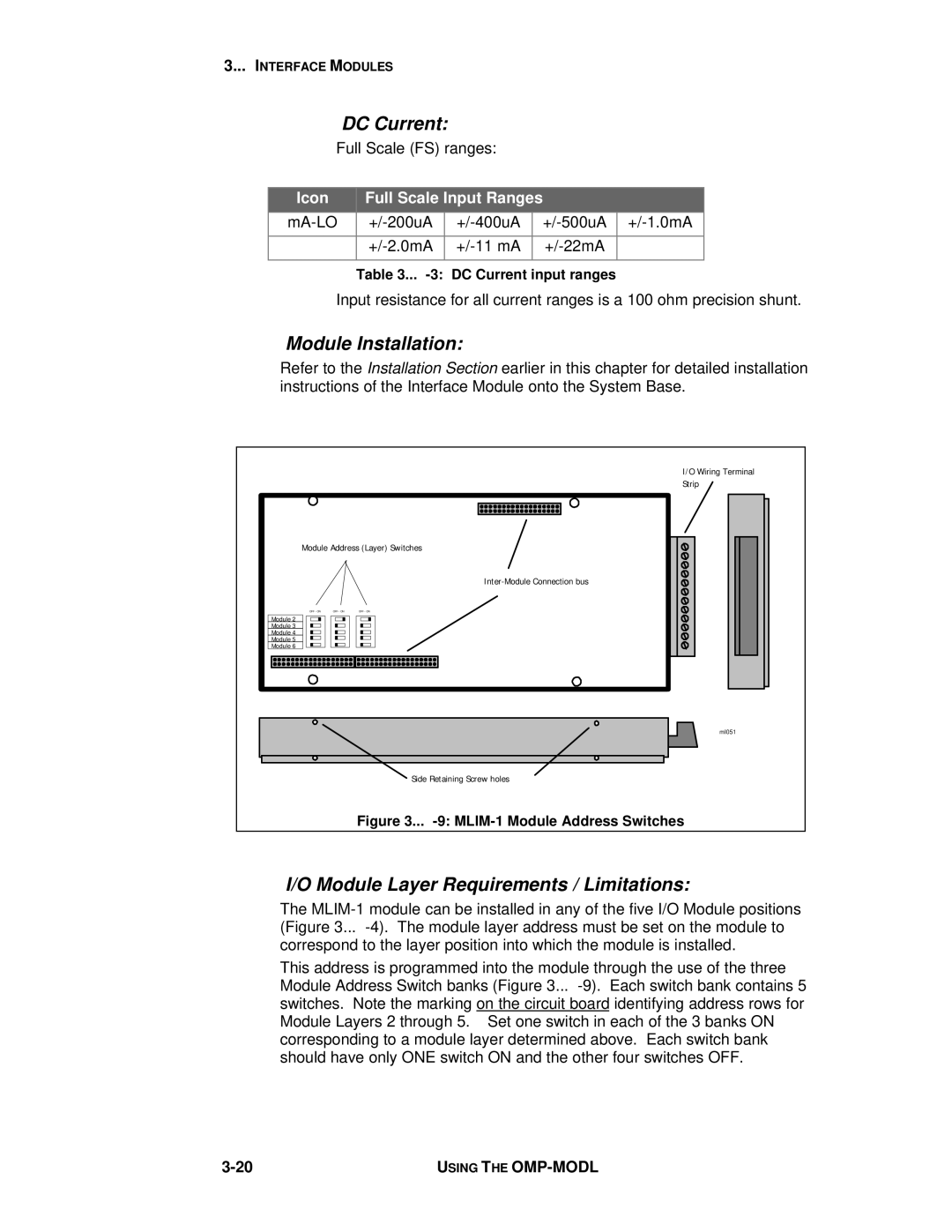
Refer to the Installation Section earlier in this chapter for detailed installation instructions of the Interface Module onto the System Base.
| I/O Wiring Terminal |
| Strip |
Module Address (Layer) Switches | |
| |
OFF - ONOFF - ON | OFF - ON |
Module 2 |
|
Module 3 |
|
Module 4 |
|
Module 5 |
|
Module 6 |
|
| ml051 |
| Side Retaining Screw holes |
| Figure 3... |
I/O Module Layer Requirements / Limitations:
The
This address is programmed into the module through the use of the three Module Address Switch banks (Figure 3...
USING THE |