3... INTERFACE MODULES
Frequency Signal Connection:
To utilize an
CAUTION: Note that a direct connection exists between the common
Figure 3... -22). When connecting to multiple frequency sources sharing a common ground or reference, insure that the source’s ground or reference is connected to the terminal strip `common’ terminal to prevent shorting out of the frequency signal and possible damage to the MLIM-2.
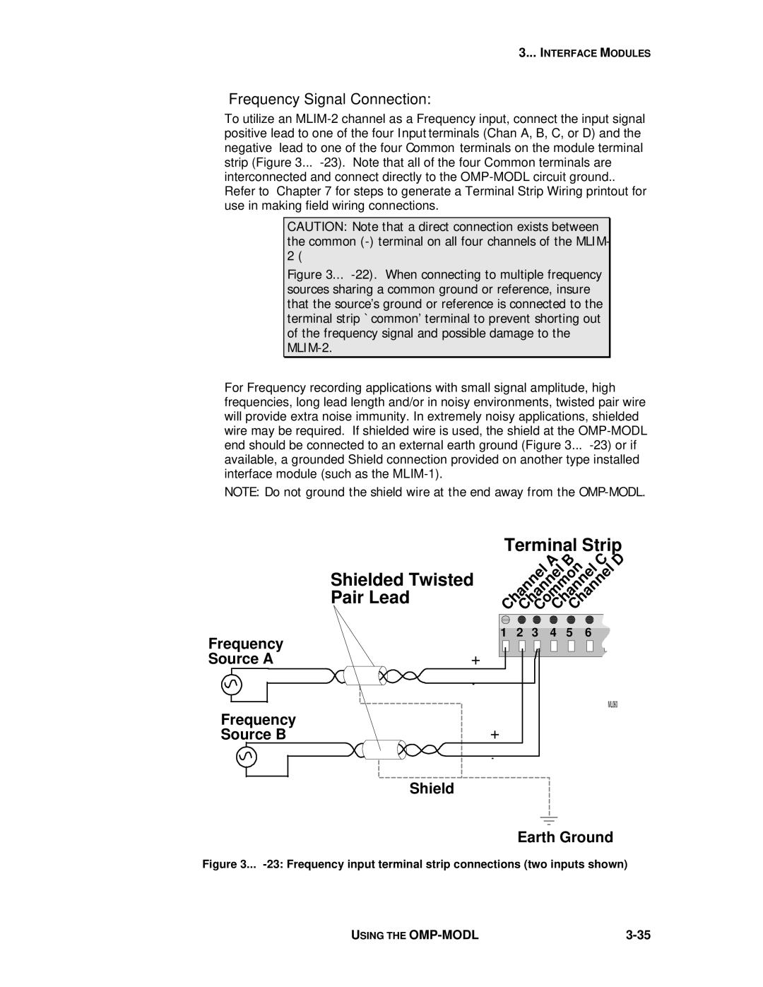
For Frequency recording applications with small signal amplitude, high frequencies, long lead length and/or in noisy environments, twisted pair wire will provide extra noise immunity. In extremely noisy applications, shielded wire may be required. If shielded wire is used, the shield at the
NOTE: Do not ground the shield wire at the end away from the
Terminal Strip
Shielded Twisted Pair Lead
|
|
|
|
| A B |
|
| C | D | ||||||||||
ChannelChannelCommonChannelChannel |
|
|
|
|
|
|
| ||||||||||||
|
|
|
|
|
|
|
|
|
|
|
|
|
|
|
|
|
|
|
|
|
|
|
|
|
|
|
|
|
|
|
|
|
|
|
|
|
|
|
|
Frequency | 1 | 2 | 3 | 4 | 5 | 6 |
+ |
|
|
|
|
| |
Source A |
|
|
|
|
| |
| - |
|
|
|
|
|
|
|
|
|
|
| ML060 |
Frequency | + |
|
|
|
|
|
Source B |
|
|
|
|
| |
| - |
|
|
|
|
|
| Shield |
|
|
|
|
|
|
| Earth Ground | ||||
Figure 3... -23: Frequency input terminal strip connections (two inputs shown)
USING THE |