3... INTERFACE MODULES
plastic bags.
INSTALLATION
When shipped, Interface Modules are provided with side screws and any necessary accessories. If ordered with a logger, the Interface Modules are typically factory installed in the System Base before shipment.
The Interface Modules stack onto the System Base building a `layered’ logger to meet the User’s needs. All modules (except the
To add a module, perform the following steps and any special Installation Instructions detailed in the following Interface Module specific sections.
1.Review the Interface Module instructions and observe any special installation instructions. These may include setting Module Address Switches and Input Configuration Switches.
2.Turn the
3.Determine the Port (layer) at which the new Interface Module is to be installed. Refer to Figure 3...
Also note that many modules require a Module address to be programmed through the setting of one or more Module Address Switches. This is covered in detail in the module specific sections that follow.
4.Remove the four side retaining screws (Figure 3...
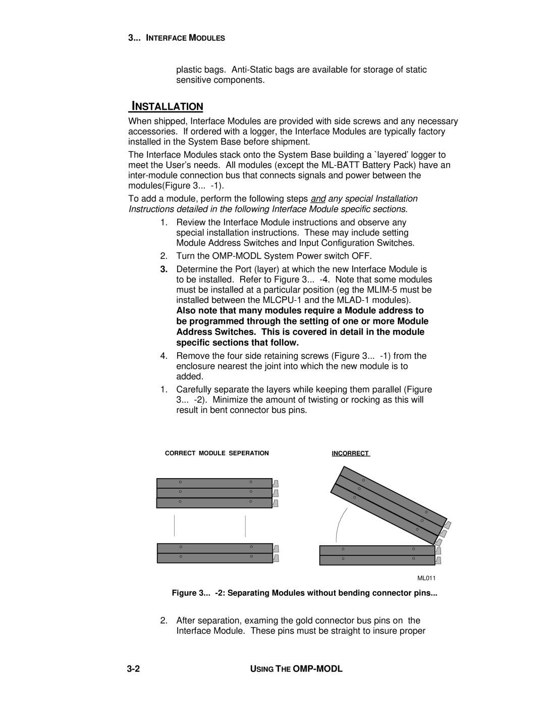
1.Carefully separate the layers while keeping them parallel (Figure 3...
CORRECT MODULE SEPERATION |
| INCORRECT | ||
|
|
|
|
|
|
|
|
|
|
|
|
|
|
|
|
|
|
|
|
|
|
|
|
|
|
|
|
|
|
|
|
|
|
|
|
|
|
|
|
|
|
|
|
|
|
|
|
|
|
ML011
Figure 3... -2: Separating Modules without bending connector pins...
2.After separation, examing the gold connector bus pins on the Interface Module. These pins must be straight to insure proper
USING THE |