3... INTERFACE MODULES
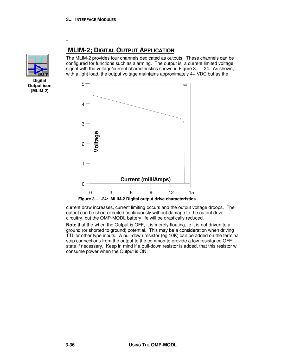
MLIM-2; DIGITAL OUTPUT APPLICATION
The
Digital | 5 |
|
|
|
|
|
Output icon |
|
|
|
| HL023 | |
|
|
|
|
|
| |
| 4 |
|
|
|
|
|
| 3 | Voltage |
|
|
|
|
| 2 |
|
|
|
| |
|
|
|
|
|
| |
| 1 |
|
|
|
|
|
| 0 |
| Current (milliAmps) |
| ||
|
|
|
|
|
| |
| 0 | 3 | 6 | 9 | 12 | 15 |
| Figure 3... | |||||
current draw increases, current limiting occurs and the output voltage droops. The output can be short circuited continuously without damage to the output drive circuitry, but the
Note that the when the Output is OFF, it is merely floating, ie it is not driven to a ground (or shorted to ground) potential. This may be a consideration when driving TTL or other type inputs. A
USING THE |