3... INTERFACE MODULES
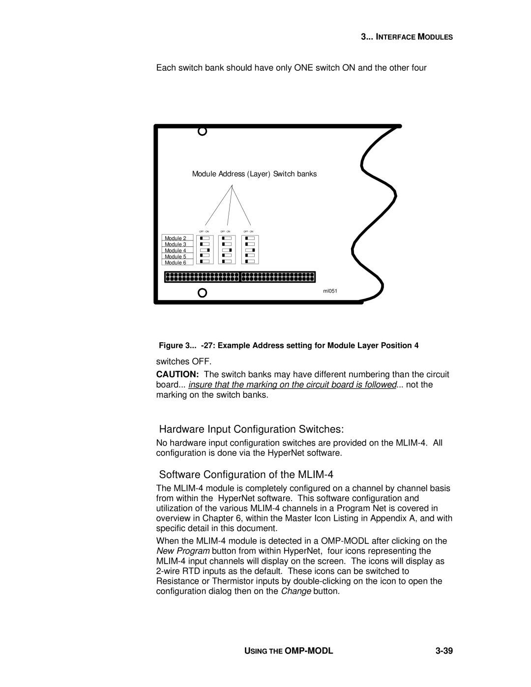
Each switch bank should have only ONE switch ON and the other four
Module Address (Layer) Switch banks
OFF - ON | OFF - ON | OFF - ON |
Module 2
Module 3
Module 4
Module 5
Module 6
ml051
Figure 3... -27: Example Address setting for Module Layer Position 4
switches OFF.
CAUTION: The switch banks may have different numbering than the circuit board... insure that the marking on the circuit board is followed... not the marking on the switch banks.
Hardware Input Configuration Switches:
No hardware input configuration switches are provided on the
Software Configuration of the MLIM-4
The
When the
USING THE |
