Omega Vehicle Security manual Constructing a OMP-MODL Program NET for Hypertrack, 10-2

Models: OMP-MODL

1 297
Download 297 pages 51.3 Kb
Page 151
Image 151

Figure 10... -

2:Probe Point icon

10... HYPERTRACK™ R EAL-TIME DATA DISPLAY

2.From within HyperTrack, construct a real-time HyperTrack Net. (Note that this is a different Net than the Program Netuploaded into the OMP-MODL memory. The HyperTrack Net runs on the PC)

3.Establish the serial connection between the PC and the OMP-

MODL

4.Enable real-time tracking

CONSTRUCTING A OMP-MODL PROGRAM NET FOR

HYPERTRACK

A OMP-MODL that is to be used in the real-time tracking mode must be programmed with a Program Net that incorporates Probe Point icons. The Probe Point icons are connected to nodes within the Program Net that the User may want to monitor through HyperTrack. Not all nodes with Probe Point icons must be displayed on the PC during HyperTrack, however any node to be monitored must have a Probe Point icon.

Probe Point icons can be given a Name via the conventional icon configuration dialog box. This name is used as a column heading during real-time tracking (see the Master Icon Reference in Appendix A).

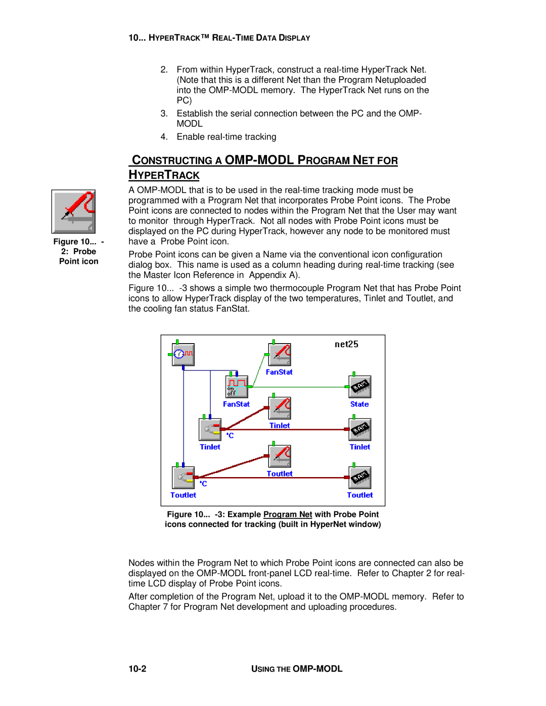
Figure 10... -3 shows a simple two thermocouple Program Net that has Probe Point icons to allow HyperTrack display of the two temperatures, Tinlet and Toutlet, and the cooling fan status FanStat.

Figure 10... -3: Example Program Net with Probe Point icons connected for tracking (built in HyperNet window)

Nodes within the Program Net to which Probe Point icons are connected can also be displayed on the OMP-MODL front-panel LCD real-time. Refer to Chapter 2 for real- time LCD display of Probe Point icons.

After completion of the Program Net, upload it to the OMP-MODL memory. Refer to Chapter 7 for Program Net development and uploading procedures.

10-2

USING THE OMP-MODL

Page 151
Image 151
Omega Vehicle Security manual Constructing a OMP-MODL Program NET for Hypertrack, 10-2