11.. . APPENDIX A: MASTER ICON REFERENCE
COUNTER INPUT ICON (DIGITAL I/O WITH MLIM-2)
FUNCTION:
Event / Counter / Frequency input and Digital output functions are all provided with the
The same dialog is used to configure the four input channels for Event, Frequency, and Counter functions.
As a COUNTER input, the
The
INPUTS:
Hardware: No signal input shown on Net for Program Net connections. The
Update: The accumulated count is output every time an Update command is received on the Update input. To preclude the loss of data, this Update command (from a connected Sample Rate Clock ) should be received before the icon counts to 16,777,216 or the counter will
Enable: Processing of the icon is allowed when Enable pin is unconnected or connected and the Enable signal is TRUE.
OUTPUTS:
Output Signal: Data type signal (ie Count totals)
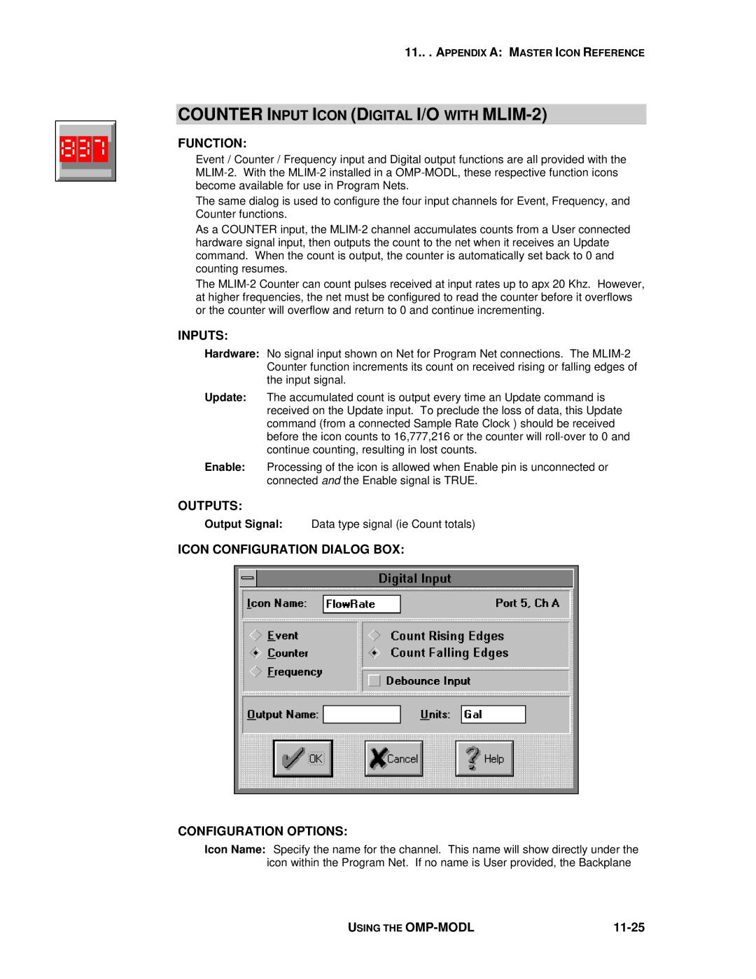
ICON CONFIGURATION DIALOG BOX:
CONFIGURATION OPTIONS:
Icon Name: Specify the name for the channel. This name will show directly under the icon within the Program Net. If no name is User provided, the Backplane
USING THE |
|