11.. . APPENDIX A: MASTER ICON REFERENCE
FREQUENCY INPUT ICON (DIGITAL I/O WITH MLIM-2)
FUNCTION:
Event / Counter / Frequency input and Digital output functions are all provided with the
The same dialog is used to configure the channel for Event, Frequency, and Counter functions.
As a FREQUENCY input, the
Calculation of the input signal frequency requires longer for lower frequencies. Due to this effect, the speed of execution of a Program Net may be reduced when reading low frequency inputs. (eg 10Hz inputs will require approximately 100mS to read, whereas a 100Hz input will require only 10mS)
NOTE: Due to the advanced signal processing utilized in the frequency mode, unbalanced
INPUTS:
Hardware: No signal input shown on Net for Program Net connections.
Update: The measured frequency is output every time an Update command is received on the Update input.
Enable: Processing of the icon is allowed when Enable pin is unconnected or connected and the Enable signal is TRUE.
OUTPUTS:
Output Signal: Data type signal, Frequency in Hz.
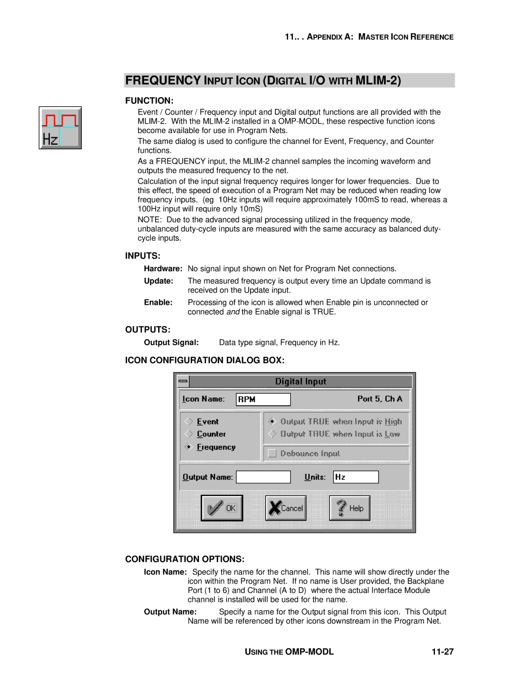
ICON CONFIGURATION DIALOG BOX:
CONFIGURATION OPTIONS:
Icon Name: Specify the name for the channel. This name will show directly under the icon within the Program Net. If no name is User provided, the Backplane Port (1 to 6) and Channel (A to D) where the actual Interface Module channel is installed will be used for the name.
Output Name: Specify a name for the Output signal from this icon. This Output Name will be referenced by other icons downstream in the Program Net.
USING THE |
|