Omega Vehicle Security OMP-MODL manual Input

Models: OMP-MODL

1 297
Download 297 pages 51.3 Kb
Page 46
Image 46

3... INTERFACE MODULES

Hardware Input Signal Configuration Switches:

Four sets of Input Configuration Switches are provided for each of the four channels (Figure 3... -11). Through the use of these switches, various types of signals can be directly fed into the OMP-MODL eliminating the need for User supplied external precision dividers, shunts and other circuitry.

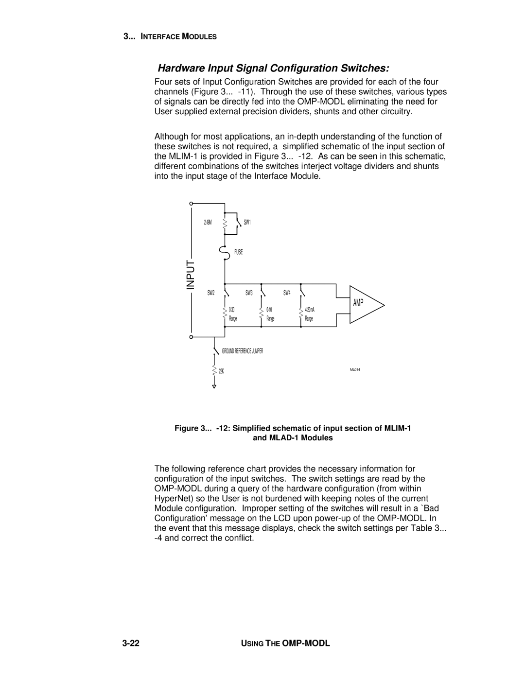
Although for most applications, an in-depth understanding of the function of these switches is not required, a simplified schematic of the input section of the MLIM-1 is provided in Figure 3... -12. As can be seen in this schematic, different combinations of the switches interject voltage dividers and shunts into the input stage of the Interface Module.

2.49M

INPUT

SW2

SW1

FUSE

SW3

SW4

0-30 Range

0-10 Range

AMP

4-20mA Range

GROUND REFERENCE JUMPER

22K

ML014


Figure 3... -12: Simplified schematic of input section of MLIM-1

and MLAD-1 Modules

The following reference chart provides the necessary information for configuration of the input switches. The switch settings are read by the OMP-MODL during a query of the hardware configuration (from within HyperNet) so the User is not burdened with keeping notes of the current Module configuration. Improper setting of the switches will result in a `Bad Configuration’ message on the LCD upon power-up of the OMP-MODL. In the event that this message displays, check the switch settings per Table 3...

-4 and correct the conflict.

3-22

USING THE OMP-MODL

Page 46
Image 46
Omega Vehicle Security OMP-MODL manual Input