3... INTERFACE MODULES
nearly the same level of error compensation as the
Due to the fact that only one of the lead wires resistance is actually measured and the other lead wire is assumed to match, in using the
3-Wire Terminal Strip Connections:
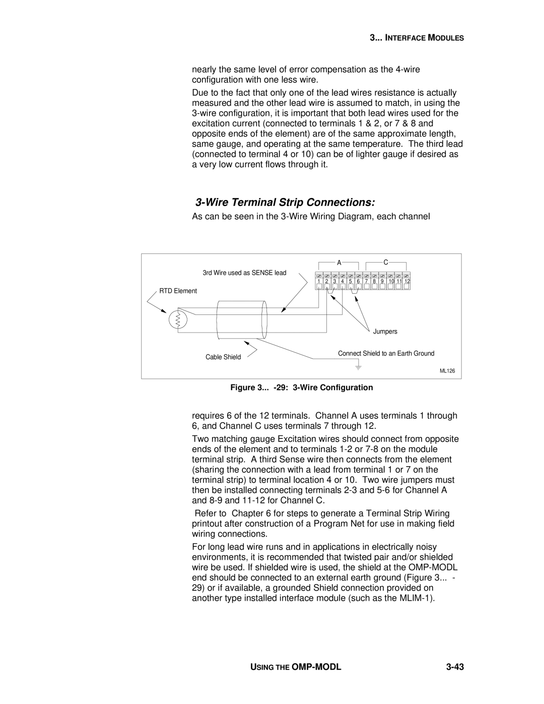
As can be seen in the 3-Wire Wiring Diagram, each channel
|
|
|
| A |
|
|
|
|
| C |
3rd Wire used as SENSE lead |
|
|
|
|
|
|
|
|
|
|
| 1 | 2 | 3 | 4 | 5 | 6 | 7 | 8 | 9 | 10 11 12 |
RTD Element |
|
|
|
|
|
|
|
|
|
|
|
|
|
|
|
|
|
| Jumpers | ||
Cable Shield |
|
|
| Connect Shield to an Earth Ground | ||||||
|
|
|
|
|
|
|
|
|
| |
|
|
|
|
|
|
|
|
|
| ML126 |
Figure 3... |
|
| ||||||||
requires 6 of the 12 terminals. Channel A uses terminals 1 through 6, and Channel C uses terminals 7 through 12.
Two matching gauge Excitation wires should connect from opposite ends of the element and to terminals
Refer to Chapter 6 for steps to generate a Terminal Strip Wiring printout after construction of a Program Net for use in making field wiring connections.
For long lead wire runs and in applications in electrically noisy environments, it is recommended that twisted pair and/or shielded wire be used. If shielded wire is used, the shield at the
29)or if available, a grounded Shield connection provided on another type installed interface module (such as the
USING THE |