2...
TIP: For applications utilizing loggers equipped with a large number of
Interface Modules, the stack can become rather tall. In these applications, side plate mounting may be desired. Contact LBI for details on the side mounting bracket..
MLCPU-1 MODULE
Overview
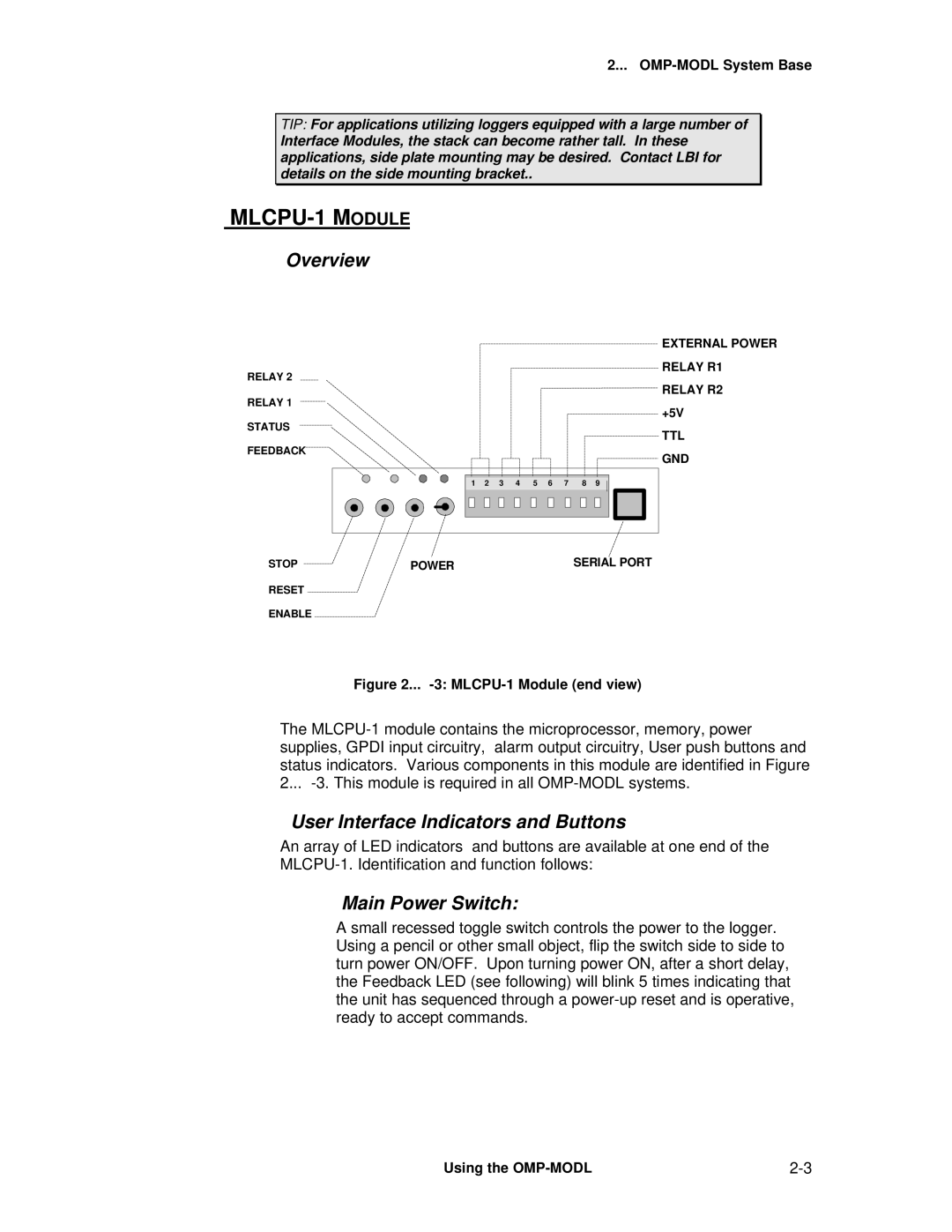
RELAY 2
RELAY 1
STATUS
FEEDBACK
EXTERNAL POWER
RELAY R1
RELAY R2
+5V
TTL
GND
1 | 2 | 3 | 4 | 5 | 6 | 7 | 8 | 9 |
STOP | POWER | SERIAL PORT |
RESET
ENABLE
Figure 2... -3: MLCPU-1 Module (end view)
The
User Interface Indicators and Buttons
An array of LED indicators and buttons are available at one end of the
Main Power Switch:
A small recessed toggle switch controls the power to the logger. Using a pencil or other small object, flip the switch side to side to turn power ON/OFF. Upon turning power ON, after a short delay, the Feedback LED (see following) will blink 5 times indicating that the unit has sequenced through a
Using the |