3... INTERFACE MODULES
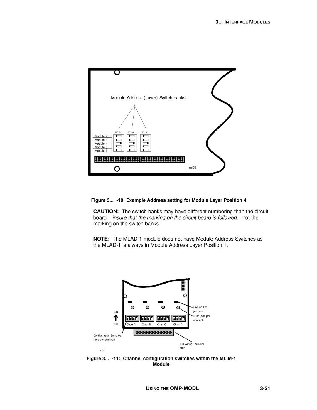
Module Address (Layer) Switch banks
OFF - ON | OFF - ON | OFF - ON |
Module 2
Module 3
Module 4
Module 5
Module 6
ml051
Figure 3... -10: Example Address setting for Module Layer Position 4
CAUTION: The switch banks may have different numbering than the circuit board... insure that the marking on the circuit board is followed... not the marking on the switch banks.
NOTE: The
|
|
|
| Ground Ref |
ON |
|
|
| jumpers |
|
|
|
| Fuse (one per |
|
|
|
| channel) |
OFF | Chan A | Chan B | Chan C | Chan D |
Configuration Switches (one per channel)
I/O Wiring Terminal
Strip
ml013
Figure 3... -11: Channel configuration switches within the MLIM-1
Module
USING THE |
