3... INTERFACE MODULES

negative lead to one of the four Common terminals on the module terminal strip (Figure 3... -33). Note that all of the four Common terminals on the terminal strip (3, 6, 9, 12) are interconnected and connect directly to the OMP-MODL circuit ground. Refer to Chapter 7 for steps to generate a Terminal Strip Wiring printout for use in making field wiring connections.

CAUTION: Note that a direct connection exists between the common (-) terminal on all eight channels of the MLIM-8. When connecting to multiple event signal sources sharing a common ground or reference, insure that the source’s ground or reference is connected to the terminal strip `common’ terminal to prevent shorting out of the source signal and possible damage to the MLIM-8.

For most event applications, shielding is not necessary due to the relatively low input impedance of the channel and the high noise immunity of the MLIM-8 channel input.

MLIM-8; DIGITAL OUTPUT APPLICATION
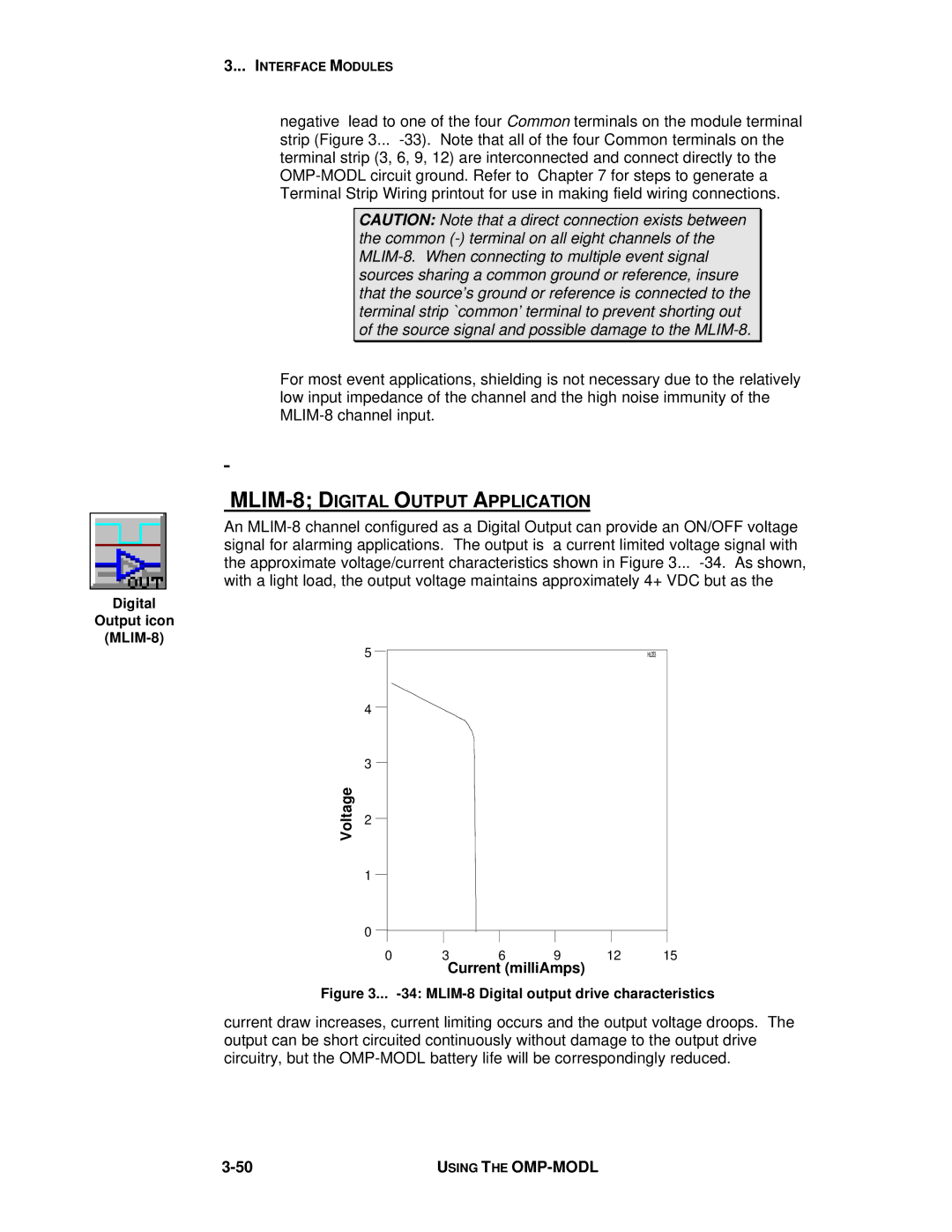
An MLIM-8 channel configured as a Digital Output can provide an ON/OFF voltage signal for alarming applications. The output is a current limited voltage signal with the approximate voltage/current characteristics shown in Figure 3... -34. As shown, with a light load, the output voltage maintains approximately 4+ VDC but as the

Digital

Output icon

(MLIM-8)

Voltage

5


HL033


4

3

2

1

0

0

3

6

9

12

15

Current (milliAmps)

Figure 3... -34: MLIM-8 Digital output drive characteristics

current draw increases, current limiting occurs and the output voltage droops. The output can be short circuited continuously without damage to the output drive circuitry, but the OMP-MODL battery life will be correspondingly reduced.

3-50

USING THE OMP-MODL

Page 74
Image 74
Omega Vehicle Security OMP-MODL manual MLIM-8 Digital Output Application, Voltage, Current milliAmps