Figure 3... -
21:
Frequency
icon
3... INTERFACE MODULES
CAUTION: Note that a direct connection exists between the common
Figure 3... -22). When connecting to multiple event or counter signal sources sharing a common ground or reference, insure that the source’s ground or reference is connected to the terminal strip `common’ terminal to prevent shorting out of the source signal and possible damage to the MLIM-2.
For most counter and event applications, shielding is not necessary due to the relatively low input impedance of the channel and the high noise immunity of the
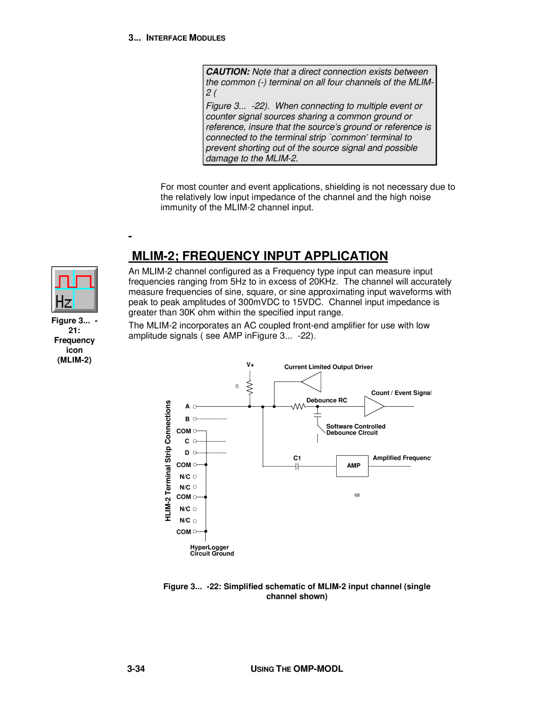
MLIM-2; FREQUENCY INPUT APPLICATION
An
The
| V+ | Current Limited Output Driver | ||
|
| |||
| R1 |
| Count / Event Signal | |
|
|
| ||
Connections | C |
| Debounce RC | |
| A |
|
| |
| B |
|
| |
| COM |
| Software Controlled | |
Strip |
| Debounce Circuit | ||
D | C1 | Amplified Frequency | ||
| ||||
| COM | |||
Terminal |
| AMP | ||
N/C |
|
| ||
|
|
| ||
| N/C |
|
| |
2- | COM |
| ML059 | |
|
| |||
|
|
| ||
HLIM | N/C |
|
| |
|
|
| ||
| N/C |
|
| |
| COM |
|
| |
| HyperLogger |
|
| |
| Circuit Ground |
|
| |
Figure 3... -22: Simplified schematic of MLIM-2 input channel (single
channel shown)
USING THE |