11.. . APPENDIX A: MASTER ICON REFERENCE
EVENT INPUT ICON (DIGITAL I/O WITH MLIM-8)
FUNCTION:
Event input and Digital output functions are all provided with the
As an EVENT input, the icon samples the state of the User connected hardware input signal (HI or LO) each time an Update command is received. The icon output state is updated when the input state changes.
This channel/icon can be changed to a Digital Output channel by selecting the Change this channel to an Output button.
INPUTS:
Hardware: No signal input shown on icon for Program Net connections.
Update: The input is sampled every time an Update command is received on the Update input. If the input state has changed since the last Update command was received, the Output is updated with the new state. The absolute time resolution of the state change is determined by the frequency of the Update command. For example, if an Update command is received every second, the state change will be recorded with one second resolution.
Enable: Processing of the icon is allowed when Enable pin is unconnected or connected and the Enable signal is TRUE.
OUTPUTS:
Output Signal: | Logic type signal |
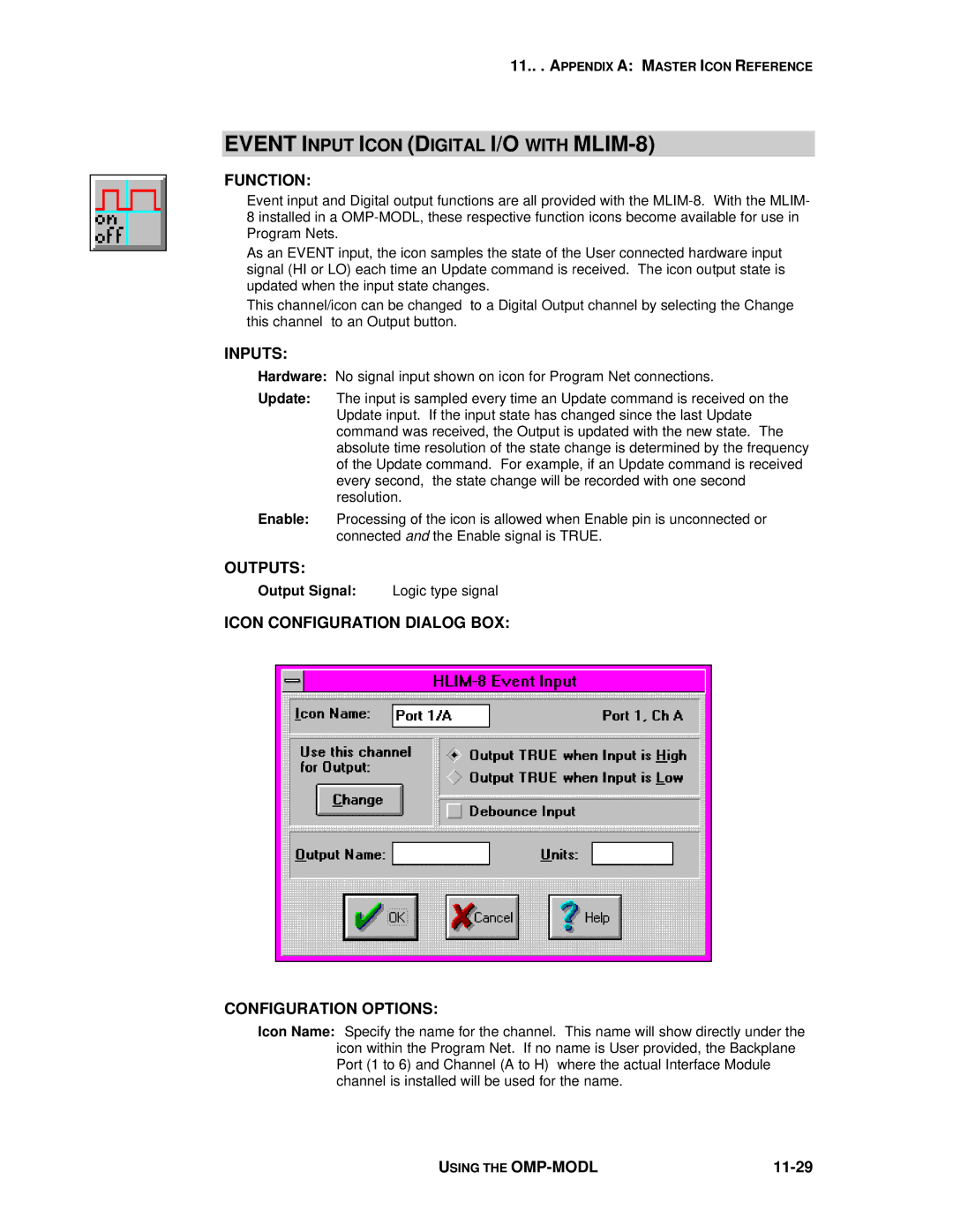
ICON CONFIGURATION DIALOG BOX:
CONFIGURATION OPTIONS:
Icon Name: Specify the name for the channel. This name will show directly under the icon within the Program Net. If no name is User provided, the Backplane Port (1 to 6) and Channel (A to H) where the actual Interface Module channel is installed will be used for the name.
USING THE |
|